
Signal receiver with a duty-cycle controller

a technology of duty-cycle controller and signal receiver, which is applied in the direction of receiver monitoring, transmission monitoring, electrical equipment, etc., can solve the problems of even more dominant problems, and achieve the effect of space and cost saving, effective attenuation or even complete compensation

Active Publication Date: 2016-08-16
THE SWATCH GRP RES & DEVELONMENT LTD
View PDF6 Cites 2 Cited by
  • Summary
  • Abstract
  • Description
  • Claims
  • Application Information

AI Technical Summary

Benefits of technology

[0009]It is therefore an object of the present invention to provide an improved signal receiver, in particular for receiving radio-frequency signals, wherein the effect of higher harmonics from an oscillator having a reference resonator can be effectively attenuated or even completely compensated. The solution should be rather space and cost efficient. Furthermore, the solution should not affect the general operation and function of the signal receiver and of its various components.

Problems solved by technology

This problem becomes even more dominant when the signal receiver is implemented in a single integrated circuit.
This device needs operating simultaneously a tune transmit path and a receive path for regulating the duty cycle, which is a drawback.

Method used


Image

  • Signal receiver with a duty-cycle controller
  • Signal receiver with a duty-cycle controller
  • Signal receiver with a duty-cycle controller

Examples


Embodiment Construction

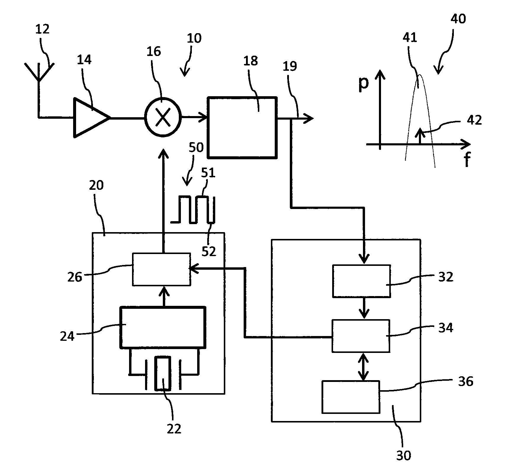
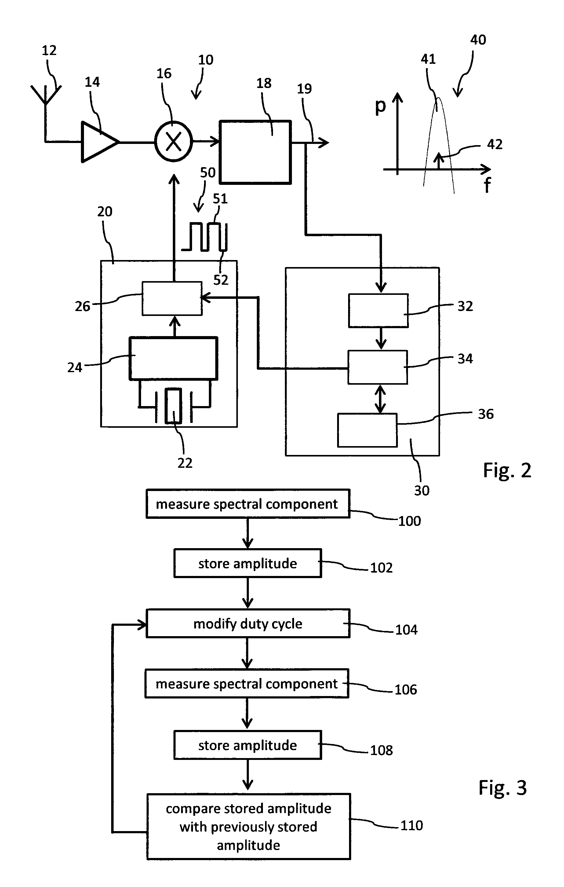
[0049]FIG. 2 shows a schematic block diagram of a signal receiver 10 according to the present invention. The signal receiver 10, typically implemented to receive radio-frequency signals comprises an antenna 12 that may operate at a carrier frequency which may be for example around 2.4 GHz. The signals received by the antenna 12 are amplified in a low noise amplifier (LNA) 14. The amplified signals are frequency converted, in particular down-converted in a mixer 16 via an oscillating signal 50 that is provided by a MEMS or crystal oscillator 20. The output of the mixer 16 is coupled with the input of a band-pass filter 18 by way of which a band 41 of interest of the intermediate signals 40 can be selected for further processing in the signal receiver 10.

[0050]The MEMS or crystal oscillator 20 comprises a signal generator 24 which is locked to a reference resonator 22. The reference resonator 22 may be a MEMS resonator or implemented by a quartz crystal or the like resonators for prov...


PUM


Abstract

The signal receiver has means to suppress at least one higher harmonic component from a MEMS or crystal oscillator having a reference resonator in filtered intermediate signals of a signal receiver. The signal receiver comprises an antenna for receiving electromagnetic signals, a low noise amplifier for amplifying signals received by the antenna, one MEMS or crystal oscillator comprising a reference resonator to generate an oscillating signal with a predefined duty-cycle, a mixer for mixing the amplified and received signals with the oscillating signal to generate intermediate signals, a band-pass filter to filter the intermediate signals, and a duty-cycle controller coupled to the MEMS or crystal oscillator and coupled to the output of the band-pass filter to analyze the spectrum of the filtered intermediate signals and to modify the duty-cycle of the oscillating signal in response to the spectrum analysis of the filtered intermediate signals.

Description

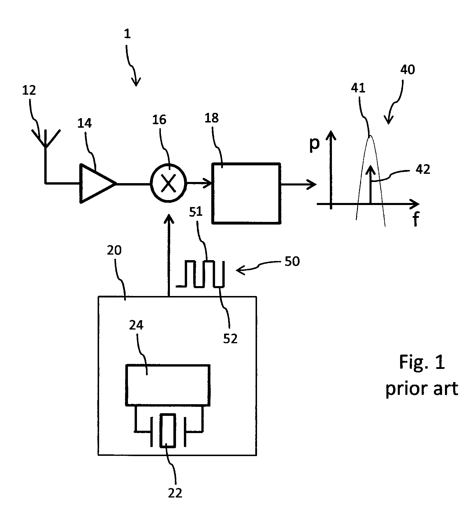
[0001]The application claims priority from European Patent Application No. 13191280.0 filed Nov. 1, 2013, the entire disclosure of which is hereby incorporated herein by reference.FIELD OF THE INVENTION[0002]The present invention relates to the field of signal receivers, in particular to receivers for radio-frequency signals. The invention also relates to a respective method of suppressing of at least one higher harmonic component from an oscillator having a reference resonator in intermediate signals of a signal receiver.BACKGROUND AND PRIOR ART[0003]For transmission of electromagnetic signals, in particular of radio-frequency signals suitable receivers are required.[0004]A conventional receiver design is for instance illustrated in FIG. 1. The signal receiver 1 comprises an antenna 12 for receiving electromagnetic signals. The antenna 12 is connected with a low noise amplifier (LNA) 14 that is adapted to amplify the signals received by the antenna 12. The LNA is further connected ...

Claims


Application Information

Patent Timeline
Patent Type & Authority Patents(United States)
IPC IPC(8): H04B17/00H04B15/06H04B1/10
CPCH04B15/06H04B1/1027H04B17/0062H04B17/29H04B2001/1054H04B17/21H03K5/156H04B1/06
Inventor CASAGRANDE, ARNAUDVELASQUEZ, CARLOSZELLWEGER, EMIL
Owner THE SWATCH GRP RES & DEVELONMENT LTD
Learn More