Motor connecting member and motor device
a technology of connecting member and motor device, which is applied in the direction of electrical apparatus, dynamo-electric machines, supports/enclosements/casings, etc., can solve the problems of increasing device size and breaking of wire rods, and achieve the effect of convenient assembly of motor unit 1, avoiding contact with surrounding members, and facilitating vehicle assembly work
- Summary
- Abstract
- Description
- Claims
- Application Information
AI Technical Summary
Benefits of technology
Problems solved by technology
Method used
Image
Examples
first embodiment
The First Embodiment
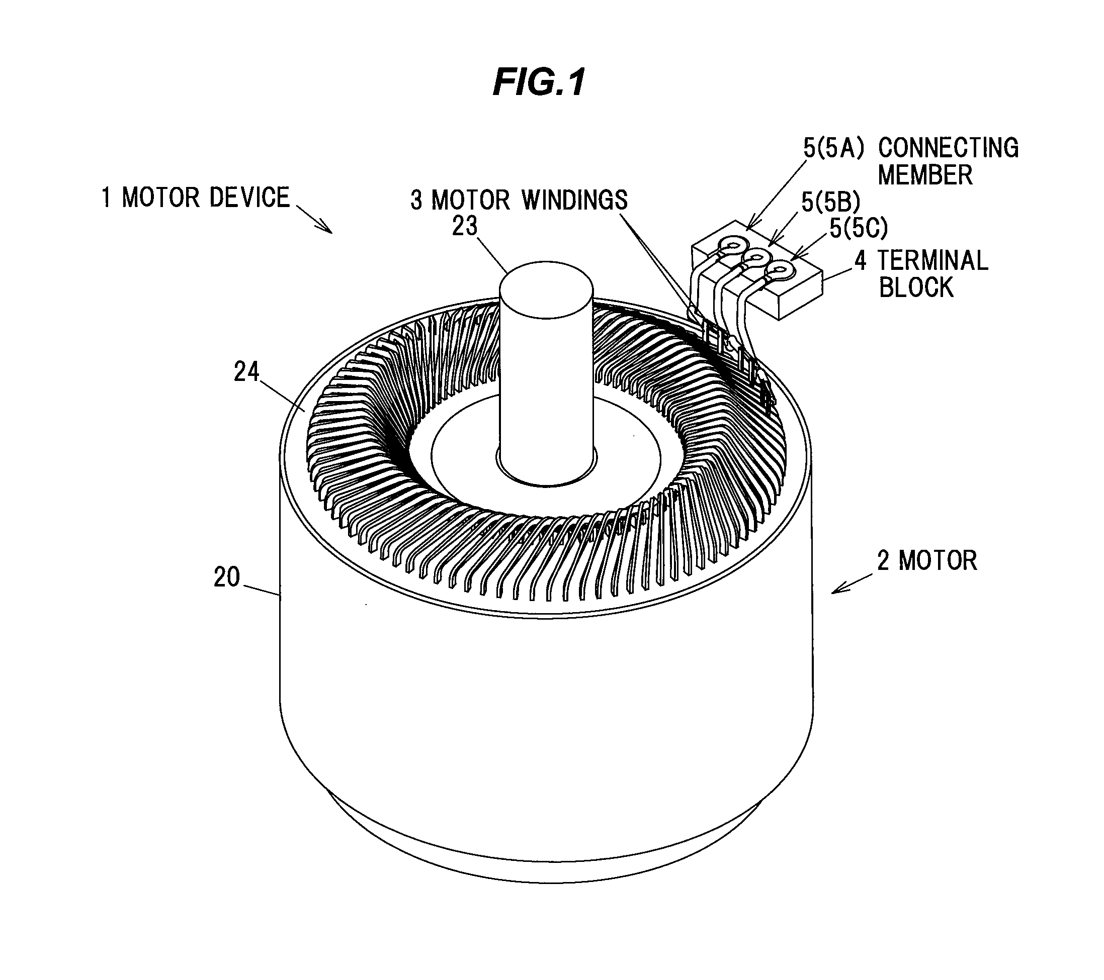
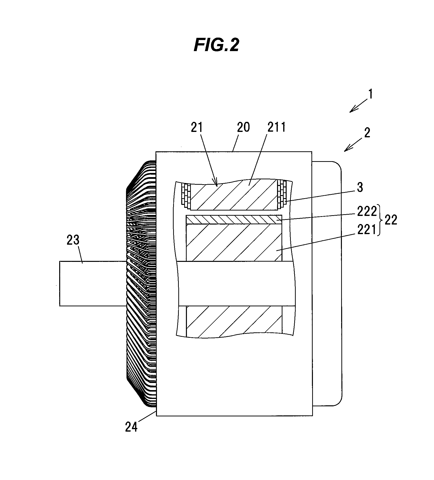
[0042]FIG. 1 is a perspective view showing a motor device in the present embodiment. FIGS. 2A and 2B are a plan view and a side view respectively showing the motor device. In FIG. 2B, a cross section in an inner portion of a motor body is shown inside a fracture area surrounded by break lines.
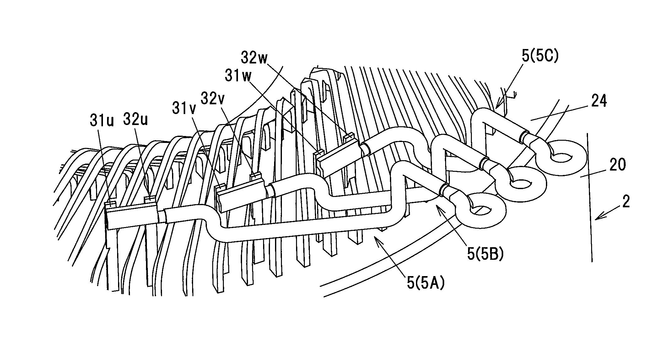
[0043]This motor device 1 is configured as including a motor 2, and a plurality (three in the present embodiment) of connecting members 5 for connections between motor windings 3 of the motor 2 and a terminal block 4. The motor 2 includes a bottomed cylindrical motor case 20, an annular stator core 21 received in the motor case 20, a rotor 22 disposed inside the stator core 21, a motor shaft 23 penetrated through the center of the rotor 22 and rotatably supported integrally with the rotor 22, and a covering member 24 made of a molded resin and covering an opening of the motor case 20.
[0044]The motor device 1 is used as, e.g., a vehicle traction driving source, and is support...
second embodiment
[0074]Next, the second embodiment of the invention will be described in reference to FIGS. 7A to 8C. Note that, the members having the same functions as those described in the first embodiment will be denoted by the common reference numerals in FIGS. 7A to 8C and the explanation thereof will be omitted.
[0075]FIGS. 7A to 7C show plural connecting members 6 (first to third connecting member 6A, 6B and 6C) in the second embodiment, wherein FIG. 7A is a front view, FIG. 7B is a perspective view and FIG. 7C is a side view. In FIG. 7B, a portion of the motor 2 in the second embodiment is shown together with the plural connecting members 6.
[0076]The motor 2 is provided with the motor case 20 having a bottomed cylindrical shape and the lid member 24 formed of mold resin and covering an opening of the motor case 20 in the same manner as the motor 2 in the first embodiment and has the same inner structure as that shown in FIG. 2 but is different in that an axial end 201 of the motor case 20 p...
third embodiment
[0084]Next, the third embodiment of the invention will be described in reference to FIGS. 9A to 10C. The third embodiment is to modify the connecting member 6 in the second embodiment so that the winding connecting portion 62 has a different shape and the remaining configuration of the connecting member 6 is the same as that of the second embodiment.
[0085]FIGS. 9A to 9C show plural connecting members 6 (first to third connecting member 6A, 6B and 6C) in the third embodiment, wherein FIG. 9A is a front view and FIGS. 9B and 9C are perspective views. FIGS. 10A to 10C show the winding connecting portion 62 of the connecting member 6 in the third embodiment, wherein FIG. 10A is a perspective view, FIG. 10B is a front view and FIG. 10C is a side view.
[0086]In the connecting member 6 of the third embodiment, the plate portion 621 at the tip portion of the winding connecting portion 62 has a flat connection surface 62a to be connected to the motor winding 3 and a back surface 62b parallel ...
PUM
 Abstract
Description
Claims
Application Information
 - R&D
- Intellectual Property
- Life Sciences
- Materials
- Tech Scout
- Unparalleled Data Quality
- Higher Quality Content
- 60% Fewer Hallucinations
Browse by: Latest US Patents, China's latest patents, Technical Efficacy Thesaurus, Application Domain, Technology Topic, Popular Technical Reports.
© 2025 PatSnap. All rights reserved.Legal|Privacy policy|Modern Slavery Act Transparency Statement|Sitemap|About US| Contact US: help@patsnap.com


