Universal smart fuze for unmanned aerial vehicle or other remote armament systems

a technology of unmanned aerial vehicles and smart fuzes, applied in the direction of electric fuzes, weapons, weapons, etc., can solve the problems of limited tactical capabilities of man-portable unmanned aerial vehicles (uavs) that can effectively, the potential for civilian casualties is relative high, and the effect of tactical capabilities

Active Publication Date: 2016-08-09
UNITED STATES OF AMERICA THE AS REPRESENTED BY THE SEC OF THE ARMY
View PDF26 Cites 16 Cited by
  • Summary
  • Abstract
  • Description
  • Claims
  • Application Information

AI Technical Summary

Benefits of technology

[0008]It is still a further object of the invention to provide communicated images from an on board camera on an unmanned aerial vehicle to help an operator ascertain if a select target is an improvised explosive device (IED), or an enemy fortification.
[0009]It is yet another object of the invention to provide circuit fuze means for an operator to remotely determine safe launch, good flight, ascertain wind conditions, also to remotely arm / disarm an unmanned aerial vehicle, to fire its explosives, or to have the unmanned aerial vehicle successfully reach a select target.

Problems solved by technology

Currently, there are very few Man-Portable Unmanned Aerial Vehicles (UAV) that can effectively identify and neutralize light-armored targets or Improvised Explosive Devices (IED) with energetic warheads while minimizing collateral damage.
The lack of such tactical capabilities constrains the warfighter's ability to function in an urban environment where the targets might be in areas where the potential for civilian casualties is relative high.
However, currently such RSS systems are not equipped to then also eliminate such dangerous targets.
Often then, human soldiers must still put their lives at risk to destroy these targets after the targets have been identified by RRS or by drones.
This remains as a great risk to human life.

Method used


Image

  • Universal smart fuze for unmanned aerial vehicle or other remote armament systems
  • Universal smart fuze for unmanned aerial vehicle or other remote armament systems
  • Universal smart fuze for unmanned aerial vehicle or other remote armament systems

Examples


Embodiment Construction

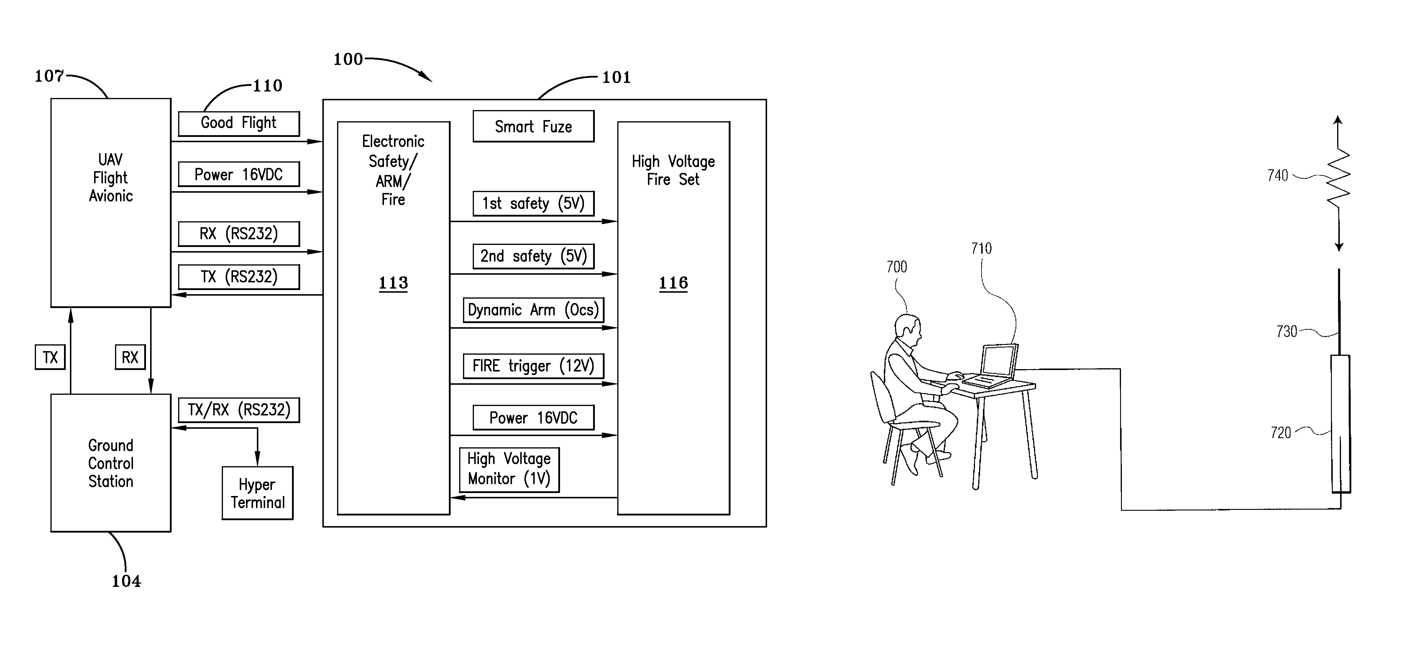
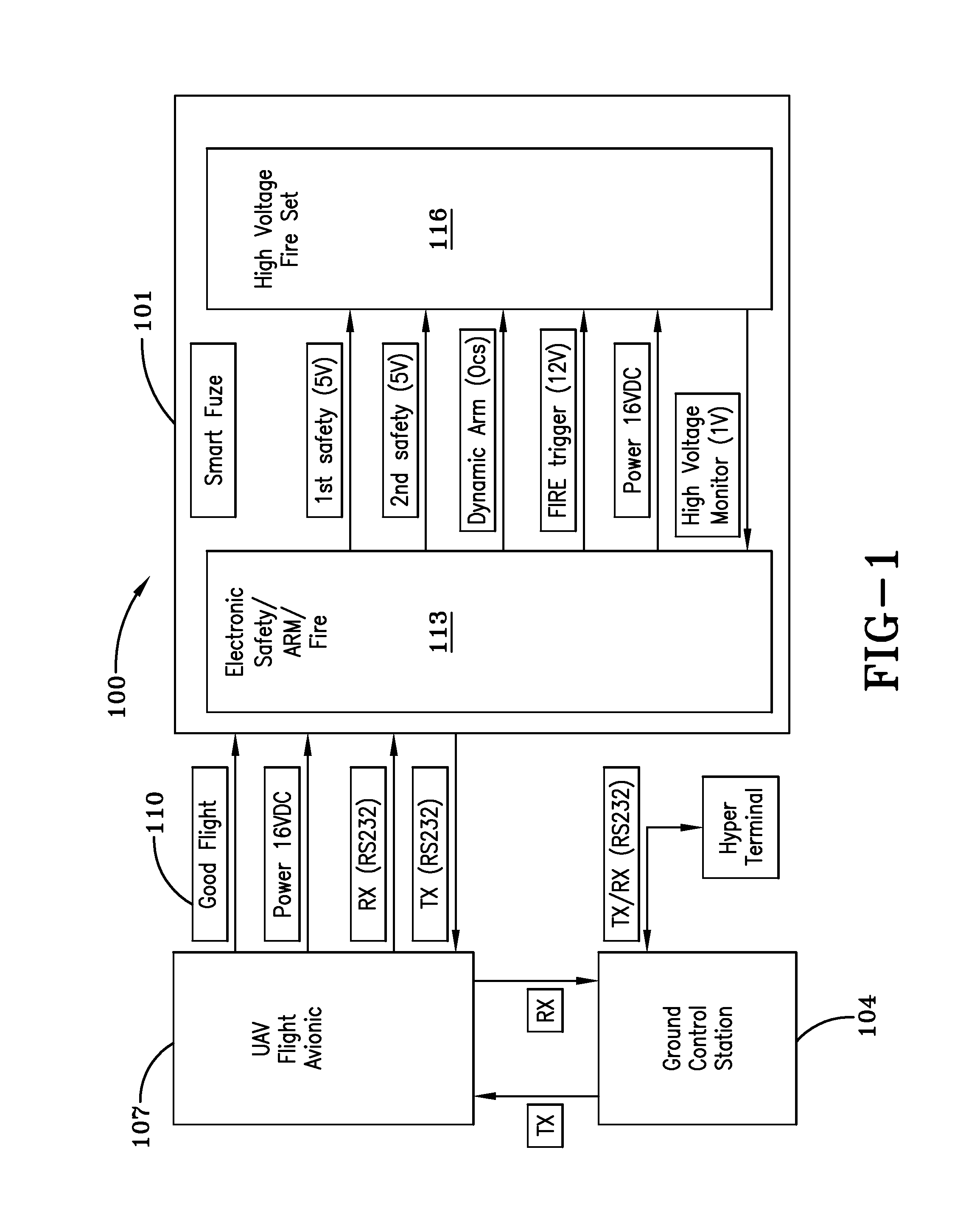
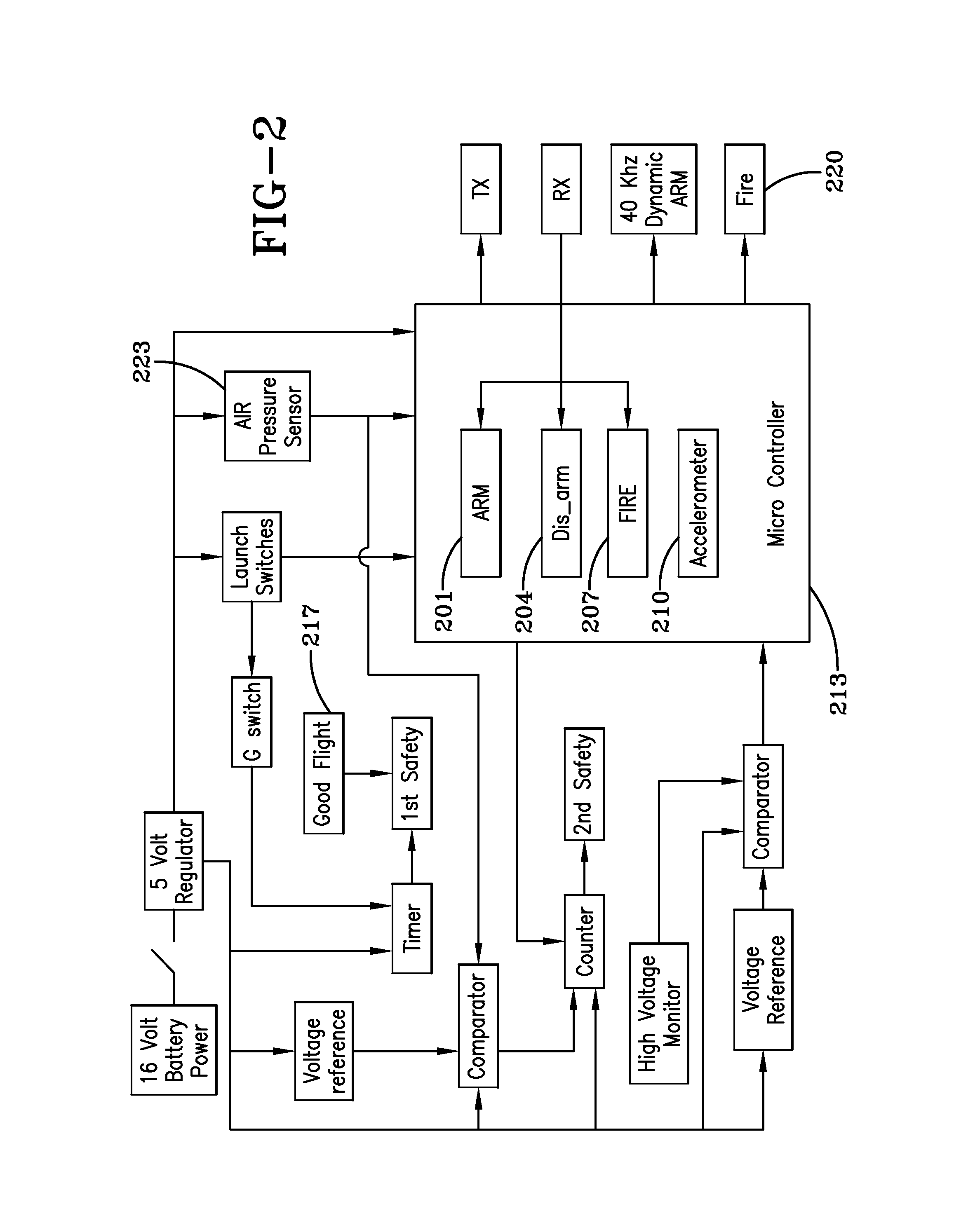
[0018]FIG. 6 shows generically an unmanned aerial vehicle, while FIG. 7 shows hypothetically a generalized ground processor unit 710 operated by a human operator 700, generating generalized signals 740 over a hypothetical antenna 730 (with aid of generalized telemetry 720) and also receiving signals over the antenna for communication, to control for example an unmanned aerial vehicle in a real time environment. FIGS. 1-3 help illustrate desired operation of the UAV of this invention in block diagram form. FIG. 4 (which is comprised of sections FIG. 4A, FIG. 4B, FIG. 4C and FIG. 4D) shows a schematic diagram of the Electronic Safe / Arm / Fire (ESAF) circuit portion of the new system according to the invention, and FIG. 5 (which is comprised of sections FIG. 5A and FIG. 5B) shows a schematic diagram of the High Voltage Fire Set (HVFS) circuit portion of the new system according to the invention.

[0019]The following explanations are offered for certain sections of the Fuze shown in the sch...


PUM


Abstract

An unmanned aerial vehicle is equipped to carry a payload of explosives for remote delivery upon a target. The vehicle includes a small TV camera, global positioning system, and auto pilot homing target software. The modified vehicle is capable of being detonated upon an impact or selectively while still in flight. Vehicle flight is monitored by an operation person at a ground control station. The vehicle includes universal smart fuze circuitry for enabling the multiple functions for the vehicle and for enabling communications/commands from the operator at the ground control station. The fuze continuously communicates aspects of fuze status back to the ground control station; measures flight velocity by sensing air speed of the UAV; arms/disarms an explosives warhead package in the vehicle; in flight fires the explosives or else detonates the explosives warhead package upon impact with a select target. The camera images are communicated back to the operator who can make a decision on completing/aborting a mission. The wind speed indications, also fed back to the operator, can further aid in verifying a successful launch/good flight for decision of completing/aborting a mission.

Description

CROSS REFERENCE TO RELATED APPLICATIONS[0001]This application is a continuation in part of U.S. patent application Ser. No. 13 / 097,174 filed Apr. 29, 2011 by identical inventors Lloyd Khuc et al., entitled “Universal Smart Fuze For Unmanned Aerial Vehicle Or Other Remote Armament Systems”, which in turn claimed benefit under 35 USC §119 of the filing date of U.S. Provisional Patent Application No. 61 / 331,412 filed May 5, 2010, the entire file contents of all of which applications are incorporated herein as though fully set forth. In addition, this application fully incorporates by reference the entire contents of U.S. Pat. No. 7,631,833 issued Dec. 15, 2009 to Ghaleb et al., entitled “Smart Counter Asymmetric Threat Micromunition With Autonomous Target Selection And Homing”.U.S. GOVERNMENT INTEREST[0002]The inventions described herein may be made, used, or licensed by or for the U. S. Government for U. S. Government purposes.BACKGROUND OF INVENTION[0003]Currently, there are very few...

Claims


Application Information

Patent Timeline
Patent Type & Authority Patents(United States)
IPC IPC(8): F42C15/40F42C11/00F42C15/00
CPCF42C15/40F42C11/00F42C15/00F42B15/10F42C1/04F42C15/42
Inventor KHUC, LLOYDCALI, NICHOLASVO, DANIEL
Owner UNITED STATES OF AMERICA THE AS REPRESENTED BY THE SEC OF THE ARMY
Why Eureka
Try Eureka