
Oxygen mixing valve

a technology of oxygen mixing valve and oxygen, which is applied in the direction of non-electric variable control, process and machine control, instruments, etc., can solve the problems of unstable proportional relation of air and oxygen, increased product manufacturing cost, and difficulty in the first design to precisely control the precision of the small tidal volume of the infant, etc., to achieve accurate control of ventilation volume, good mechanical structure platform, and convenient disassembly and maintenance

Inactive Publication Date: 2016-08-09
BEIJING AEONMED
View PDF10 Cites 0 Cited by
  • Summary
  • Abstract
  • Description
  • Claims
  • Application Information

AI Technical Summary

Benefits of technology

[0008]An object of the present invention is to solve the problems of high product costs, the poor sealing, the difficult production and manufacture, and the inaccurate control on the oxygen mixing proportion, and provide an oxygen mixing valve, which is advantageous for its small volume, simple structure, convenient installation and maintenance, low manufacture cost, steady and precise adjustment and control on an oxygen concentrate at high pressure, and sensitive and accurate adjustment and control on the oxygen mixing proportion. With an accompanying ordinary proportional valve, the inventive oxygen mixing valve can implement the control for a large or small tidal volume.
[0014]Further, one end of the air outlet is provided with a tapered face mated with the second ball, one end of the oxygen outlet is provided with a tapered face mated with the first ball, so that a reliable sealing can be formed and an accurate control on the ventilation volume can be realized by the fit between the tapered face and the ball, the ball driving stem is arranged in the mixing cavity, and two ends of the ball driving stem respectively extend into the air outlet and the oxygen outlet.
[0015]Further, an axis of the driving stem, a center of the first ball, an axis of the ball driving stem and a center of the second ball are on the same line, this design can ensure the accurate control on the mixing proportion of the air and the oxygen.
[0020]The present invention is advantageous as follows. The step motor is used to rotate the involute cam, which in turn drives the bearing to rotate and horizontally displace simultaneously to push and move the driving stem, so that the reliable sealing can be formed between the ball and the tapered face of the valve body and the accurate control on the ventilation volume can be realized. Further, in the case of different flows, the rotational angle of the step motor can be linearly converted into a change of the gas flow, which provides a good mechanical structure platform for achieving automation control. The sealing of the valve is safe and cost effective and is convenient in disassembly and maintenance, because of the O-shaped sealing ring used in each sealed portion in the oxygen mixing valve. Since the axis of the driving stem, the center of the first ball, the axis of the ball driving stem and the center of the second ball lie on the same line, the first ball and the second ball can be used for opening proportionately the respective outlet, thereby ensuring a high precision of the oxygen mixing valve. With the springs arranged in the oxygen mixing valve, the first guide holder and the second holder can be pre-pressed; further, the prepressing force of the second spring is greater than that of the first spring, thus ensuring that the driving stem is pressed closely on the balls at its two sides, as a result, under the normal condition, the second ball always blocks the air outlet and hence the air outlet is in the closed state; while the first ball is away from the oxygen outlet and hence the oxygen outlet is in the entirely open state. In view of the prior art, the inventive oxygen mixing valve is advantageous for its small volume, simple structure, convenient installation and maintenance, low manufacture cost, steady and precise adjustment and control on an oxygen concentrate at high pressure, and sensitive and accurate adjustment and control on the oxygen mixing proportion. With an accompanying ordinary proportional valve, the inventive oxygen mixing valve can implement the control for a large or small tidal volume.

Problems solved by technology

In the first design of such two designs, two flow proportional control valves are adopted, thus the product manufacturing cost is increased, and it is very difficult for the first design to precisely control the precision of the small tidal volume of the infant.
The second one of such two designs adopts two end-face seal valves which are demanding for the precision of manufacturing and assembling of parts, thus the manufacture becomes difficult and the sealing is not good, resulting in an unstable mixed proportional relation of the air and the oxygen.
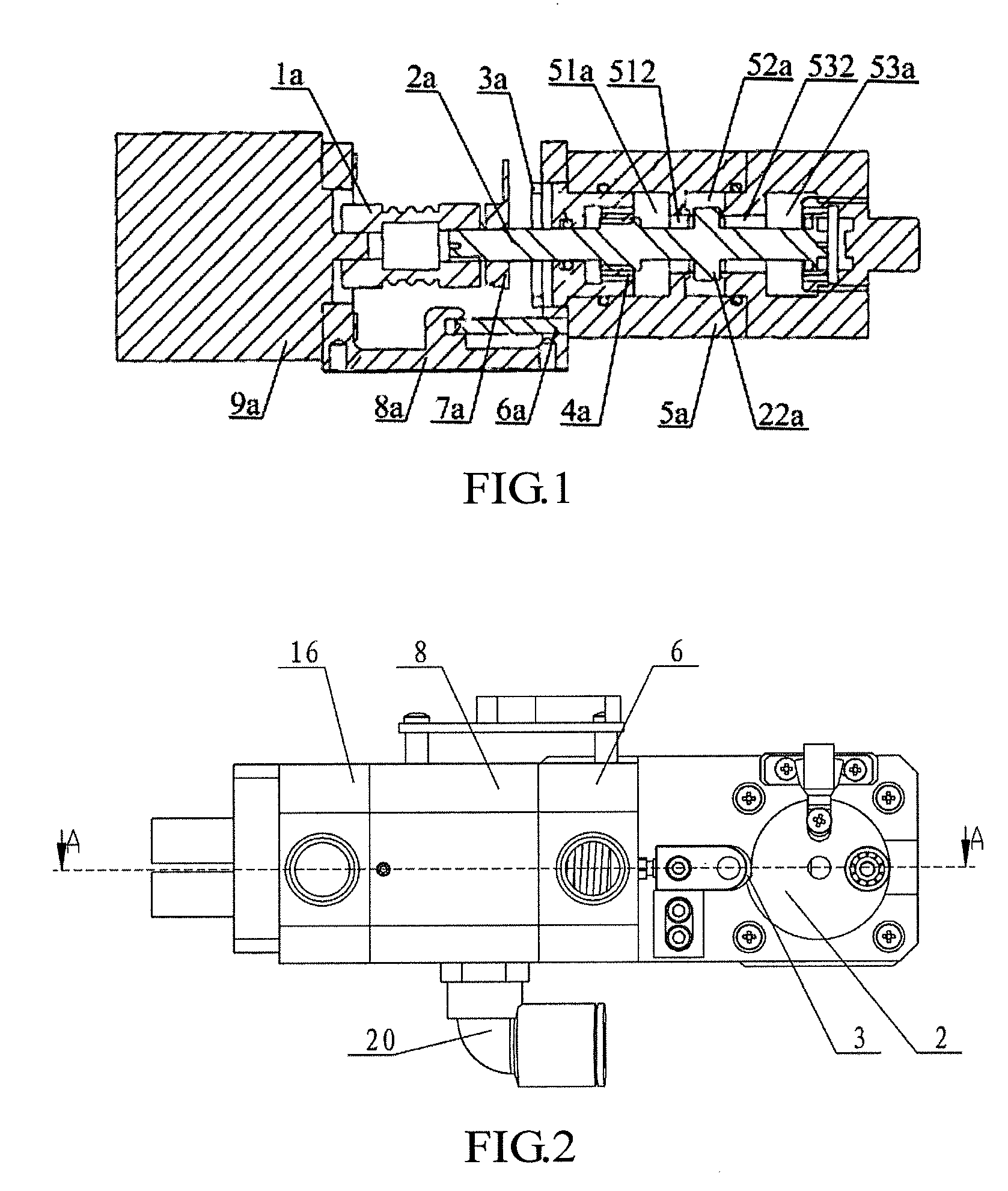
The disadvantages of the above solution lie in that: firstly, the seal effect is not good enough since the air outlet and oxygen outlet are sealed by only the end-face seal through the shoulder 22a of the core shaft 2a; secondly, such end-face seal is demanding for the flatness of the contact surfaces, thus the manufacture becomes difficult; and thirdly, it is difficult to align the center of the core shaft 2a with that of the motor shaft, such that the core shaft 2a is easily not concentric with the motor shaft, causing the poor seal between the shoulder 22a and the first gas outlet 512 or the second gas outlet 532, as a result, gas leakage is caused and the gas proportions are out of the required ranges.

Method used


Image

  • Oxygen mixing valve
  • Oxygen mixing valve
  • Oxygen mixing valve

Examples


Embodiment Construction

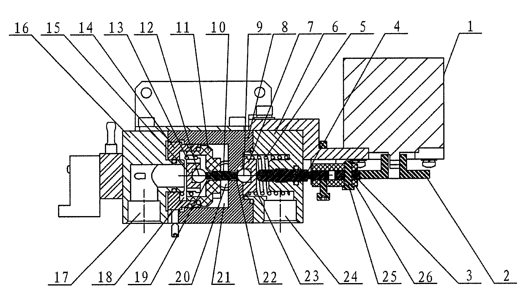
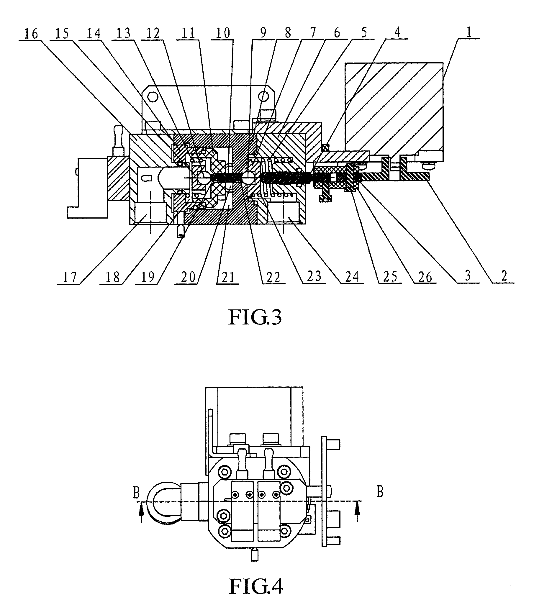
[0035]In the embodiment shown in FIGS. 2 to 6, an oxygen mixing valve according to the present invention includes a valve body having an oxygen inlet 24, an air inlet 17 and a mixed-gas outlet 20. A mixing cavity 21 in communication with the mixed-gas outlet 20, an oxygen cavity 23 in communication with the oxygen inlet 24, and an air cavity 18 in communication with the air inlet 17 are arranged in the valve body. A first guide holder 7 is elastically arranged in the oxygen cavity 23, a second guide holder 15 is elastically arranged in the air cavity 18, a first ball 9 and a second ball 12 which are contacted with a ball driving stem 10 are respectively arranged on inner sides of the first guide holder 7 and the second guide holder 15, a driving stem 4 is arranged movably on an outer side of the first guide holder 7, a rotatable bearing 3 is arranged on an outer end of the driving stem 4, and an involute cam 2 connected with an output shaft of a step motor 1 is arranged on an outer ...


PUM

PropertyMeasurementUnit
radiusaaaaaaaaaa
angleaaaaaaaaaa
displacementaaaaaaaaaa

Abstract

An oxygen mixing valve comprises a valve body. The valve body has an oxygen inlet, an air inlet, and a gas mixture outlet. A mixing chamber in communication with the gas mixture outlet, an oxygen chamber in communication with the oxygen inlet, and an air chamber in communication with the air inlet are disposed in the valve body. A first guide seat is elastically disposed in the oxygen chamber, and a second guide seat is elastically disposed in the air chamber. A first ball and a second ball are respectively disposed at inner ends of the first guide seat and the second guide seat. The first ball and the second ball are connected through a ball mandril. A mandril is movably disposed at an outer end of the first guide seat, a bearing capable of rotating is disposed at an outer side of the mandril, an involute cam is disposed at an outer side of the bearing, and the involute camis connected to an output shaft of a stepper motor. The oxygen mixing valve has advantages of simple structure, convenient mounting and maintenance, low manufacturing cost, capability of sensitively and precisely adjusting the ratio of the oxygen to air, and capability of controlling the tidal volume in conjunction with a common proportional valve.

Description

FILED OF THE INVENTION[0001]The present invention relates to the field of medical instruments, and more particularly to an oxygen mixing valve.BACKGROUND OF THE INVENTION[0002]Mechanical ventilation may be performed on a patient during the operation of a medical instrument such as a ventilator or an anesthetic machine. For a patient under treatment, especially an infant patient and a seriously ill patient, it is important to control a ventilation volume and adjust an oxygen concentration. The precision and the grade of the ventilator depend on the precision, sensitivity and continuous adjustment of an oxygen concentration with respect to both a large tidal volume of the adult and a small tidal volume of the infant.[0003]The tidal volume generally refers to the amount of air inhaled or expired during each human breath in a resting state (i.e. a state without stimulation), and depends on age, gender, volume surface, breathing habit and metabolism of the body. The preset tidal volume g...

Claims


Application Information

Patent Timeline
Patent Type & Authority Patents(United States)
IPC IPC(8): A61M16/12G05D11/13B01F5/00F16K31/524A61M16/00A61M16/20F16K11/048B01F3/02A61M39/22A61M39/24B01F23/10
CPCA61M16/12A61M16/20A61M16/0057B01F3/02G05D11/132B01F5/008F16K31/52416F16K31/52425F16K11/048A61M2039/226A61M2039/248A61M2202/0208A61M16/122A61M16/208B01F23/10B01F25/1051
Inventor JI, JINQUANWANG, JUN
Owner BEIJING AEONMED
Learn More