
Apparatus, system, and methods for mechanical energy regeneration

a mechanical energy and energy regeneration technology, applied in the field of energy storage and retrieval, can solve the problems of low combined efficiency, brayton cycle, second law loss of superheat in charging mode, gradient preheating of working fluid, etc., and achieve the effect of small second law loss

Active Publication Date: 2016-07-19
KREUGER STEN
View PDF11 Cites 31 Cited by
  • Summary
  • Abstract
  • Description
  • Claims
  • Application Information

AI Technical Summary

Benefits of technology

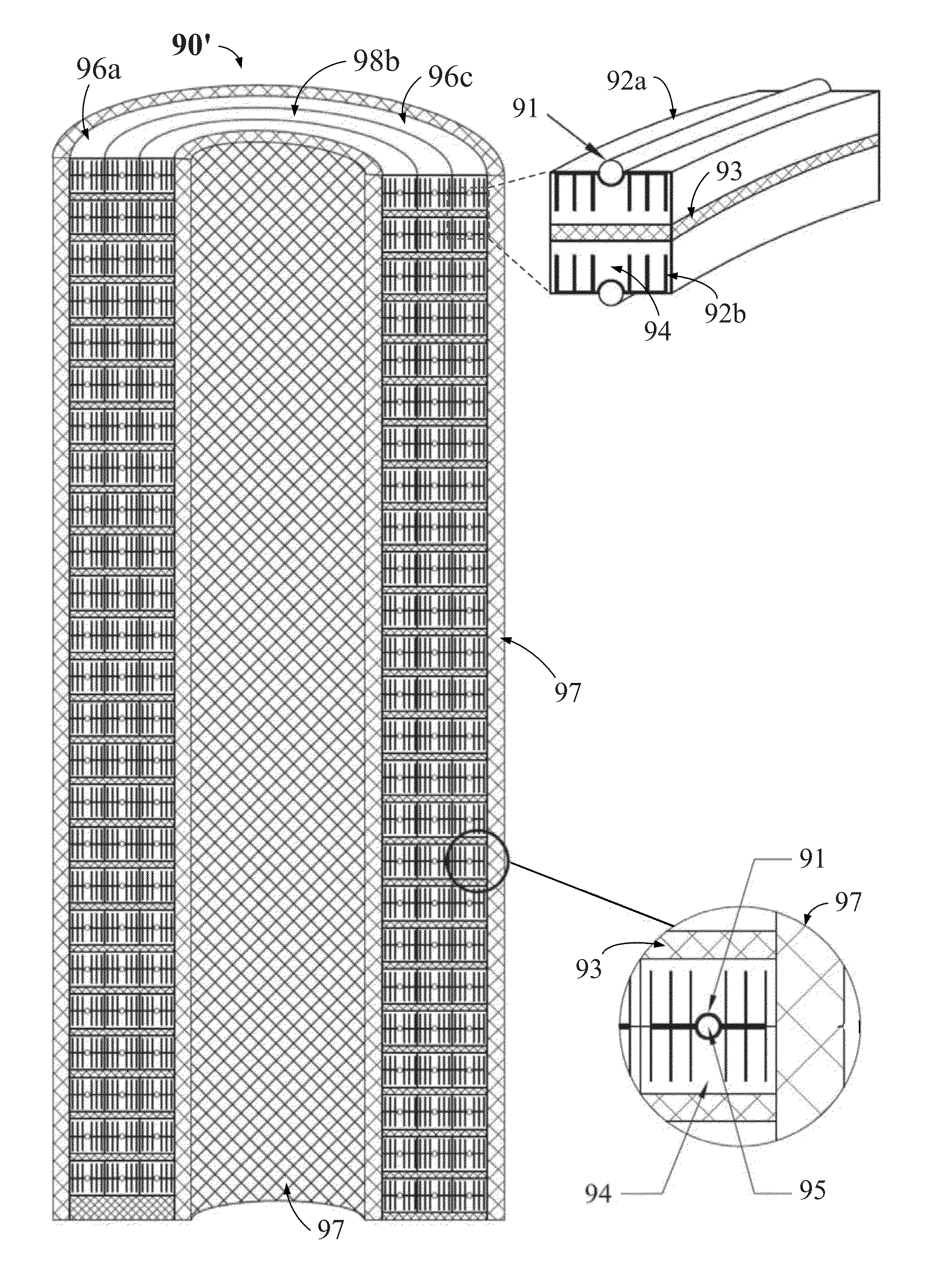
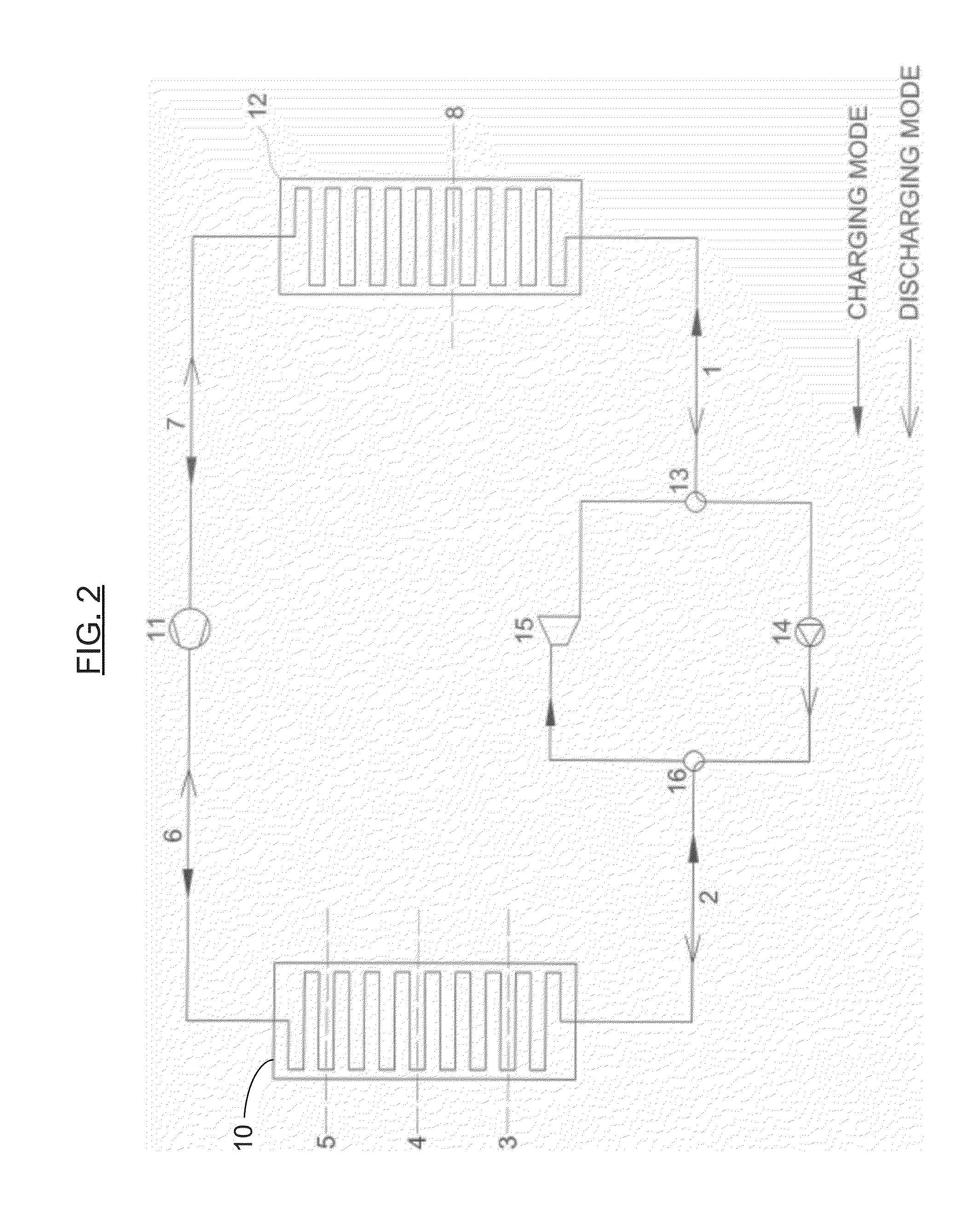
The present invention is a thermo-mechanical energy storage and retrieval system that uses solid heat storage media to adapt to changes in heat capacity in the working fluid. It provides an extended temperature range and similar compression and expansion losses as a Brayton cycle and a Rankine cycle. The system includes high and low pressure heat storage devices, which contain solid materials within a framework of pipes or tubes. The system also includes an isolation material to reduce second law losses between the layers of the tubes and external heat exchangers. The heat storage devices are integrated with a loop, and this system is advantageous in avoiding external heat exchangers and reducing heat conduction losses.

Problems solved by technology

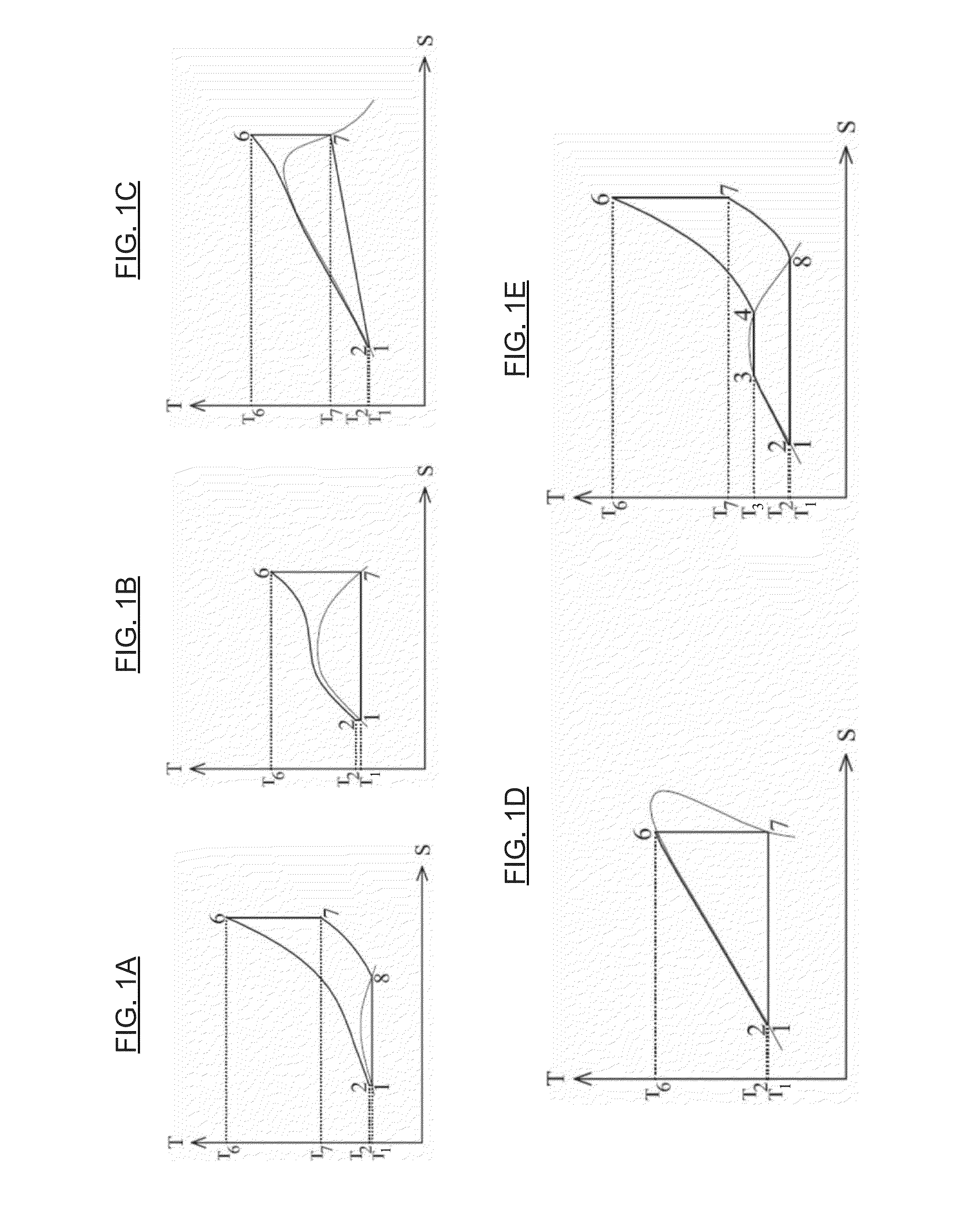
The disadvantage with Brayton cycles is low combined efficiency, with the working fluid flowing through two gas compression and two gas expansion processes in a complete charge and discharge cycle.
The disadvantage of reversible Rankine cycles is the second law losses from the superheat in charging mode and the gradient preheating of the working fluid in discharging mode.

Method used


Image

  • Apparatus, system, and methods for mechanical energy regeneration
  • Apparatus, system, and methods for mechanical energy regeneration
  • Apparatus, system, and methods for mechanical energy regeneration

Examples


Embodiment Construction

[0032]Reference will now be made in detail to various embodiments of the invention, examples of which are illustrated in the accompanying drawings. While the invention will be described in conjunction with the following embodiments, it will be understood that the descriptions are not intended to limit the invention to these embodiments. On the contrary, the invention is intended to cover alternatives, modifications and equivalents that may be included within the spirit and scope of the invention as defined by the appended claims. Furthermore, in the following detailed description, numerous specific details are set forth in order to provide a thorough understanding of the present invention. However, it will be readily apparent to one skilled in the art that the present invention may be practiced without these specific details. In other instances, well-known methods, procedures, components, and circuits have not been described in detail so as not to unnecessarily obscure aspects of th...


PUM

PropertyMeasurementUnit
Temperatureaaaaaaaaaa
Thicknessaaaaaaaaaa
Pressureaaaaaaaaaa

Abstract

Systems and methods for storing and retrieving thermo-mechanical energy are disclosed. The systems and methods generally include a thermodynamic loop or cycle (e.g., a reversible transcritical, trilateral, or Rankine / vapor compression cycle) that works as a heat pump in a charging mode and as a heat engine in a discharging mode. The thermodynamic loop or cycle includes a gas pressure changing device, a liquid pressure changing device, and a working fluid. The system further includes one or more heat storage devices with solid heat storage material(s). Heat is transferred between the working fluid and the solid heat storage material(s) in the high and low pressure sides of the thermodynamic cycle, respectively.

Description

RELATED APPLICATION(S)[0001]The present application may be related to U.S. patent application Ser. No. 14 / 512,168, filed Oct. 10, 2014, the relevant portions of which are incorporated herein by reference.FIELD OF THE INVENTION[0002]The present invention generally relates to the field of energy storage and retrieval. More specifically, embodiments of the present invention pertain to methods and systems that use thermal energy for storing and retrieving mechanical energy.DISCUSSION OF THE BACKGROUND[0003]GB Pat. No. 423093 to Marguerre (1933) disclosed the basic principle of a heat pump and a heat engine for storing mechanical energy as heat in liquid storage media and using a reversible Rankine cycle.[0004]U.S. Pat. No. 8,443,605 to Sapiem and U.S. Pat. No. 8,656,712 to Isotropic Ltd. store heat in a hot and a cold gradient storage with solid material using a Brayton cycle. EP Pat. No. 2778406 to ABB Technology AG stores energy in liquids using a Brayton cycle. WO 2010 / 145963 by ABB ...

Claims


Application Information

Patent Timeline
IPC IPC(8): F01K1/00F28D20/00F01K1/12F01K21/00F01K25/12F01K25/10F01K25/08F01K25/06F01K17/02F01K3/12F01K7/36B21D53/02
CPCF01K1/12F01K25/08F01K25/12F01K25/10F01K25/06F28D20/0056F01K21/00F01K7/36F01K3/12F01K17/02Y10T29/4935Y02E60/14
Inventor KREUGER, STEN
Owner KREUGER STEN
Learn More