Optical beam positioning unit for atomic force microscope

a positioning unit and atomic force technology, applied in scanning probe microscopy, instruments, measurement devices, etc., can solve the problems of reducing the resolution, increasing the interaction area, and limiting the resolution and scan speed of conventional probes

Active Publication Date: 2016-07-05
OXFORD INSTR ASYLUM RES INC
View PDF25 Cites 6 Cited by
  • Summary
  • Abstract
  • Description
  • Claims
  • Application Information

AI Technical Summary

Problems solved by technology

Physical laws put limits on the achievable resolution and scan speed of conventional probes, given acceptable noise levels.
This also holds true for high resolution measurements on hard samples such as inorganic crystals, since higher forces have the effect of pushing the tip into the sample, increasing the interaction area and thus lowering the resolution.
This sets a fundamental limit on scanning speed: raising the response time of the probe requires a probe with a high fR or, in the case of AC modes, a low Q.
However, using current SPMs / AFMs with probes significantly smaller than conventional ones presents difficulties.
Underfilling results in a loss of optical lever detection efficiency because the reflected beam diverges more than necessary.
Overfilling the lever means losing light and producing unwanted interference fringes due to light reflected from the sample.
The relatively large numerical aperture required to so shrink the spot results in a shallow depth of focus.
This can present problems with the refocusing necessary when replacing one probe with another or when using a probe with more than one cantilever.
In addition, the large opening angle of the incident beam used to achieve a high numerical aperture can require complex lens systems or an accumulation of lenses in close proximity to the probe.

Method used


Image

  • Optical beam positioning unit for atomic force microscope
  • Optical beam positioning unit for atomic force microscope
  • Optical beam positioning unit for atomic force microscope

Examples


Embodiment Construction

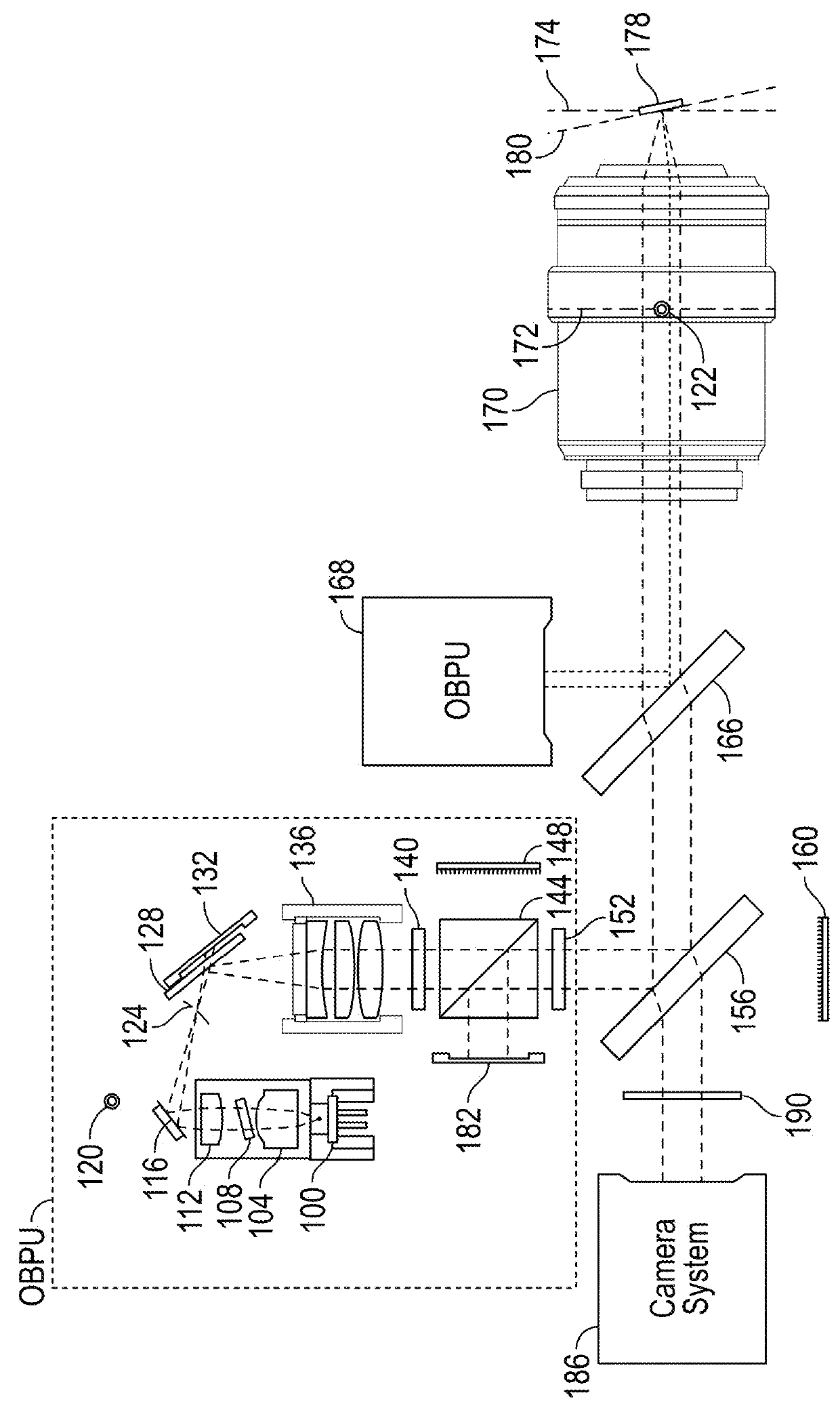
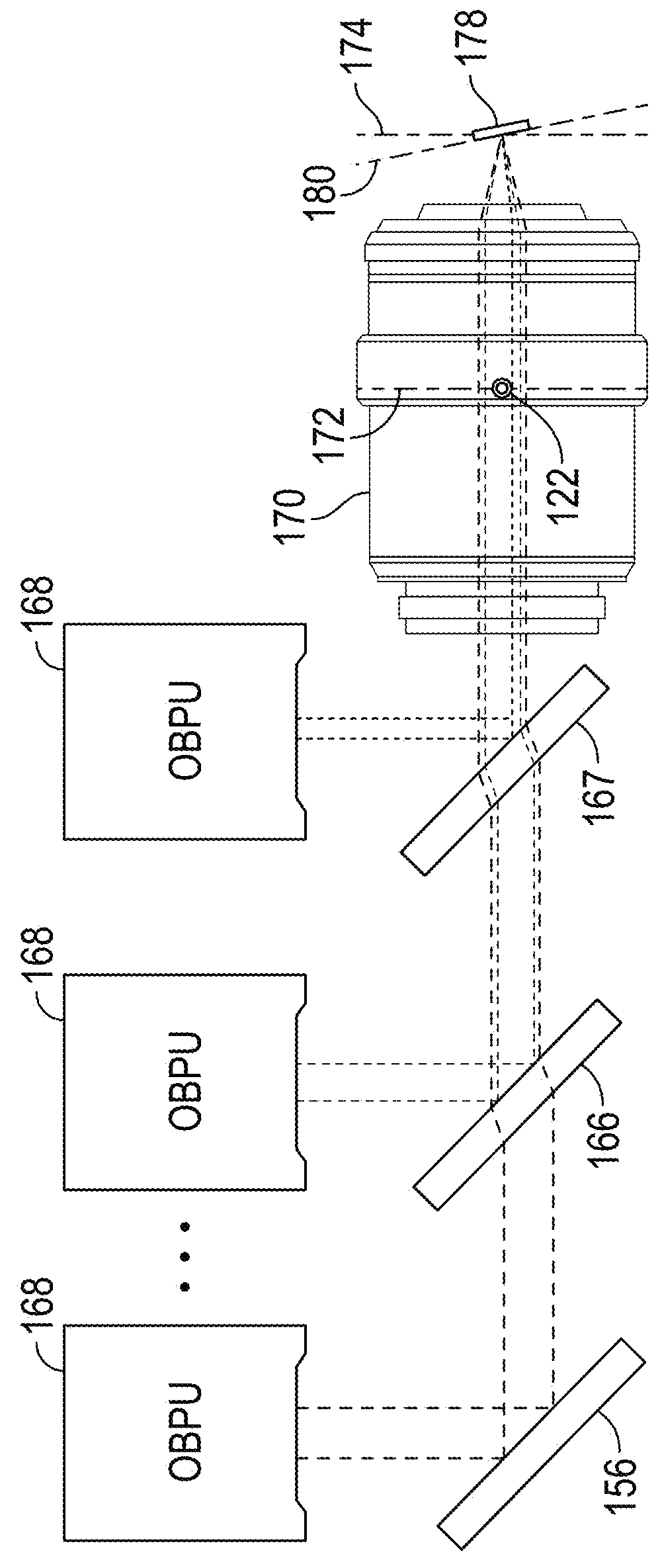
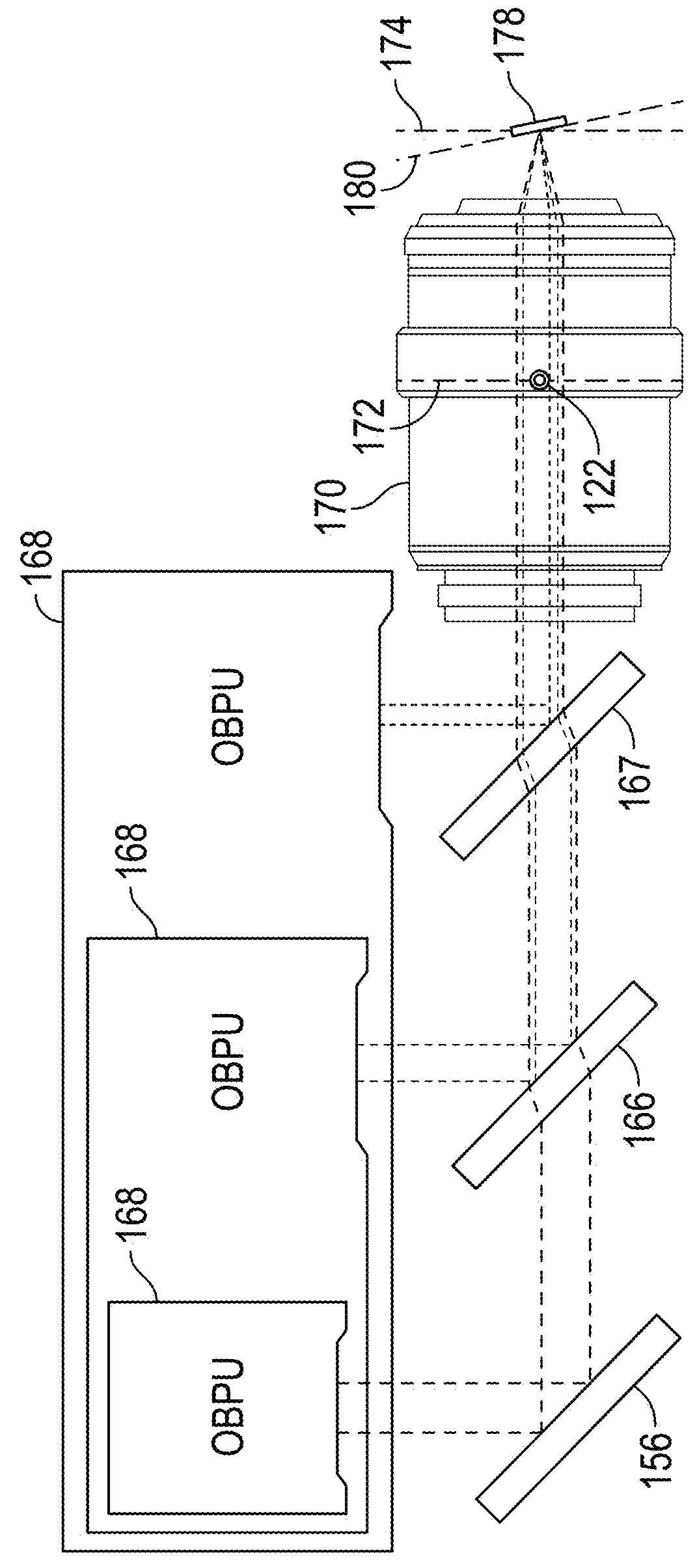
[0026]As already discussed the focused light beam in AFMs is used to measure the deflection or oscillation of the probe. It is desirable however to focus more than one light beam onto the probe to enable functionalities beyond measuring probe displacement. It is also desirable to focus more than one light beam onto the sample to enable other functionalities. The present invention resolves the design complications that stem from so focusing multiple light beams onto a single cantilever or the sample by overlapping the multiple light beams along a single optical axis of a single objective lens that is used to focus all the light beams congruently. The angular orientation or direction of travel of each light beam and the axial position of the focus of each light beam relative to the optical axis are controlled independently between light beams to allow for independent control of the three dimensional position of the focus location of each light beam relative to the cantilever or sample...


PUM


Abstract

This invention relates to an optical light beam positioning system that enables the combination of two or more light beams of different wavelengths to be focused onto a probe or sample of a scientific instrument, such as an atomic force microscope, for a number of specific uses typical to AFMs, like measuring the deflection or oscillation of the probe and illuminating an object for optical imaging, and less traditional ones like photothermal excitation of the probe, photothermal activated changes in the sample, photothermal cleaning of the probe and photochemical, photovoltaic, photothermal and other light beam induced changes in the sample. The focused light beams may be independently positioned relative to each other.

Description

BACKGROUND OF THE INVENTION[0001]Scanning probe devices such as the scanning Probe microscope (“SPM”) or atomic force microscope (“AFM”) can be used to obtain an image or other information indicative of the features of a wide range of materials with molecular and even atomic level resolution. In addition, AFMs and SPMs are capable of measuring forces accurately at the piconewton to micronewton range, in a measurement mode known as a force-distance curve or force curve. As the demand for resolution has increased, requiring the measurement of decreasingly smaller forces free of noise artifacts, the old generations of these devices are made obsolete. A demand for faster results, requiring decreasingly smaller cantilevers, only reinforces this obsolescence. The preferable approach is a new device that addresses the central issue of measuring small forces with minimal noise, while providing an array of modules optimizing the performance of the device when using small cantilevers or when ...

Claims


Application Information

Patent Timeline
Patent Type & Authority Patents(United States)
IPC IPC(8): G01Q20/02
CPCG01Q20/02G01Q60/38
Inventor LABUDA, ALEKSANDERCLEVELAND, JASONWALTERS, DERONPROKSCH, ROGER
Owner OXFORD INSTR ASYLUM RES INC
Why Eureka
Try Eureka