Imaging apparatus, control method, and storage medium storing program

a technology of image processing and control method, applied in the direction of color television details, television system details, television systems, etc., can solve the problem of user missing the next photo opportunity, and achieve the effect of smooth switching

Active Publication Date: 2016-06-14
CANON KK
View PDF8 Cites 2 Cited by
  • Summary
  • Abstract
  • Description
  • Claims
  • Application Information

AI Technical Summary

Benefits of technology

[0008]The present invention is made in view of the above problem, and the object of the present invention is to maintain a photographable display state so as not to miss a photo opportunity when a photographer performs preparation work before shooting or confirmation work after shooting. Further, the present invention is made to smoothly switch to a display state in which the photographer can perform the confirmation work after shooting whenever necessary.

Problems solved by technology

Thus, in this technology, there is a problem in that the user may miss a next photo opportunity because a certain time is necessary to restart the display on the electronic viewfinder and it takes a certain period for the digital camera to transition to a photographable state.

Method used


Image

  • Imaging apparatus, control method, and storage medium storing program
  • Imaging apparatus, control method, and storage medium storing program
  • Imaging apparatus, control method, and storage medium storing program

Examples


first embodiment

[0015]An embodiment according to the present invention will be described below with reference to drawings.

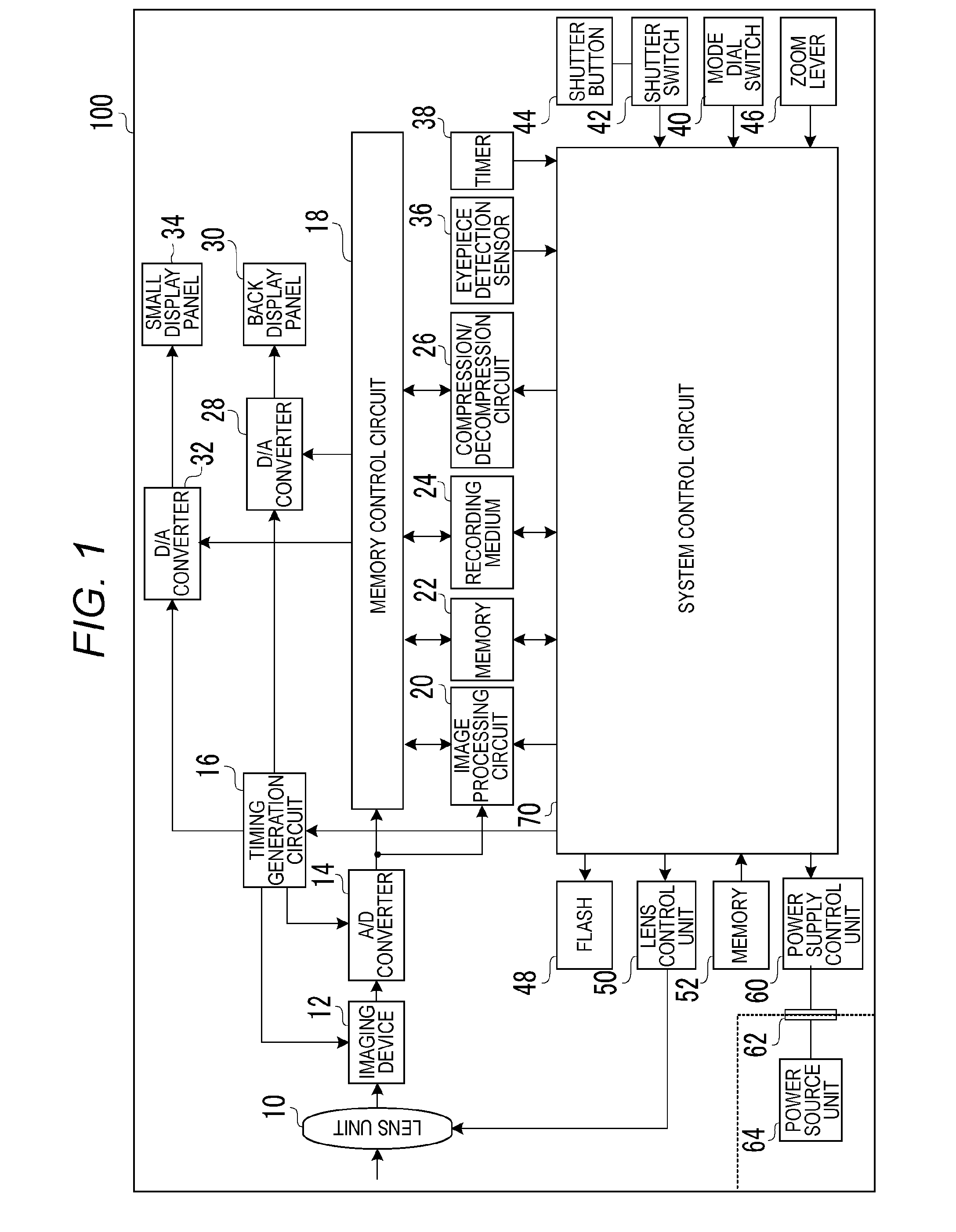
[0016]FIG. 1 is a diagram illustrating an imaging apparatus 100. A lens unit 10 includes a zoom mechanism, a stop mechanism and so on. An imaging device 12 converts an optical image to an electrical signal. An example of the imaging device 12 is a CCD device. An A / D converter 14 converts an analog output signal of the imaging device 12 to a digital signal. A timing generation circuit 16 supplies a clock signal and a control signal to the imaging device 12, the A / D converter 14, and D / A converters 28 and 32. The timing generation circuit 16 is controlled by a system control circuit 70 which will be described below.

[0017]A memory control circuit 18 controls data transfer among the A / D converter 14, an image processing circuit 20, memory 22, a recording medium 24, a compression / decompression circuit 26, and the D / A converters 28 and 32. The data output from the A / D converter 14 is ...

second embodiment

[0076]In the following, a characteristic configuration of the present embodiment will be described in detail while omitting the configuration same as the first embodiment.

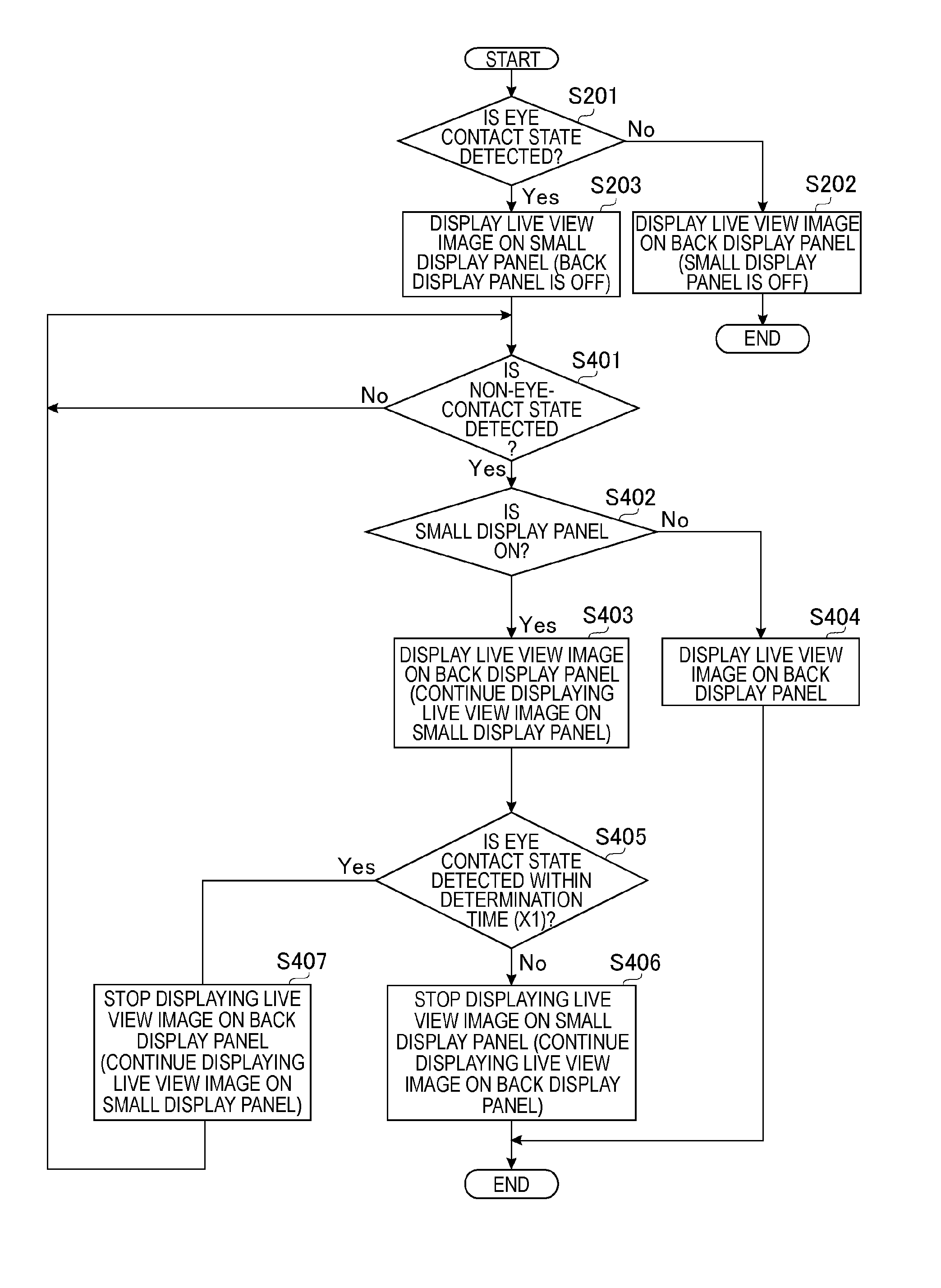
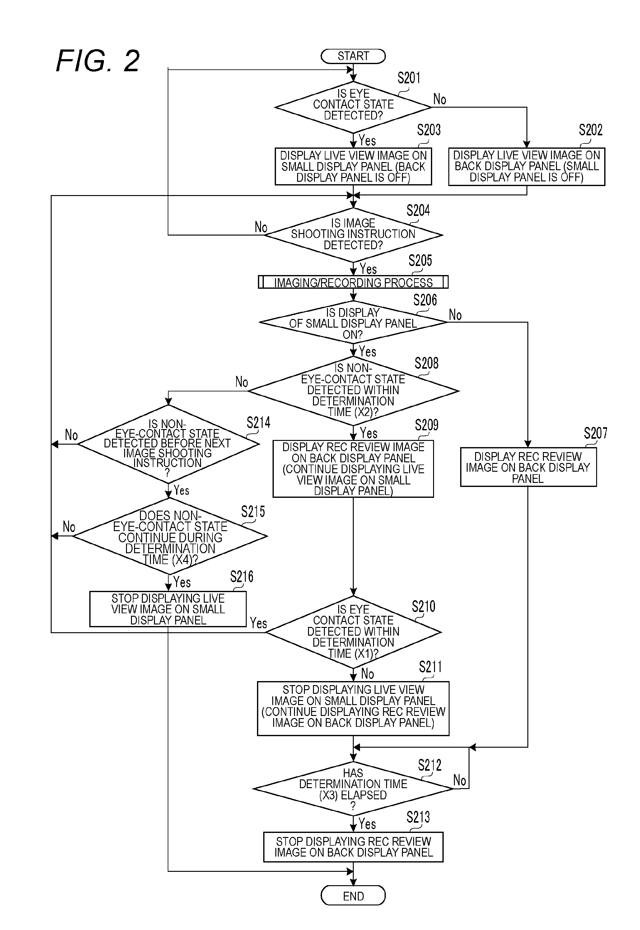
[0077]FIG. 4 is a flowchart illustrating display processing performed by an imaging apparatus 100. The imaging apparatus 100 controls displays on a back display panel 30 and a small display panel 34 in the display processing. In steps S201 to S203, processing is same as the first embodiment.

[0078]In step S401, a system control circuit 70 determines whether a state at an eyepiece viewfinder is a non-eye-contact state. More specifically, the system control circuit 70 obtains a detection result from an eyepiece detection sensor 36, and determines whether the state at the eyepiece viewfinder is an eye contact state or the non-eye-contact state based on the obtained detection result.

[0079]Next, in step S402, the system control circuit determines the display state on the small display panel 34 is ON. In the case of deter...


PUM


Abstract

The present invention is provided to maintain a photographable display state so as not to miss a photo opportunity when a photographer performs preparation work before shooting or confirmation work after shooting, and also smoothly switch to a display state in which the photographer can perform the confirmation work after shooting whenever necessary. A live view image is displayed on a first display screen when an eye contact state is detected at the eyepiece viewfinder, and a captured image is displayed on a second display screen when a non-eye-contact state is detected after receiving an image shooting instruction. When the eye contact state is not detected within a first period from detecting the non-eye-contact state, displaying the live view image on the first display screen is stopped. The live view image is displayed on the first display screen during the first period after detecting the non-eye-contact state.

Description

BACKGROUND OF THE INVENTION[0001]1. Field of the Invention[0002]The present invention present invention relates to an imaging apparatus including an eyepiece viewfinder and provided with a plurality of display panels, a control method, and a storage medium storing a program.[0003]2. Description of the Related Art[0004]In a digital camera including a display unit such as a liquid crystal panel, a captured image can be displayed and confirmed on the liquid crystal panel. This kind of the digital camera is generally provided with a REC review function to display the captured image for a prescribed period on the liquid crystal panel or the like immediately after capturing the image.[0005]Also, in recent years, a digital camera including an electronic viewfinder formed of a liquid crystal panel or the like is getting popular instead of an optical viewfinder due to the technology advancement such as miniaturization and high definition in the liquid crystal panel. The digital camera includ...

Claims


Application Information

Patent Timeline
Patent Type & Authority Patents(United States)
IPC IPC(8): H04N5/232H04N5/235
CPCH04N5/23293H04N5/23222H04N5/23245H04N5/235H04N5/23212H04N23/67H04N23/61H04N23/64H04N23/667H04N23/634H04N23/70H04N25/71
Inventor KOBAYASHI, YOSHIHIRO
Owner CANON KK
Why Eureka
Try Eureka