
Fuel-air separator and pulse dampener

a separator and fuel technology, applied in the direction of machine/engine, liquid degasification, separation process, etc., can solve the problems of difficulty starting, engine hesitation and stalling, air entrapped in the fuel, etc., and achieve the effect of effective dampening of pressure pulses and steady delivery of fuel to the engin

Active Publication Date: 2016-06-14
FORD GLOBAL TECH LLC
View PDF40 Cites 2 Cited by
  • Summary
  • Abstract
  • Description
  • Claims
  • Application Information

AI Technical Summary

Benefits of technology

The solution effectively separates air from fuel, maintaining a steady fuel delivery to the engine and reducing pressure pulsations, thereby preventing engine issues and ensuring efficient fuel system operation.

Problems solved by technology

In a motor-vehicle fuel system with high-pressure fuel injection, air entrained in the fuel can have various undesirable effects.
Such effects include engine hesitation and stalling, difficulty starting, and damage to the fuel-injection system.
First, air present in the fuel-filter housing may limit the effective filtration area of the fuel filter, causing inadequate pressurization downstream of the fuel filter at relatively high flow rates.
Second, in a modern motor-vehicle system, various components (e.g., heating components) may divert fuel from the fuel-return line back to the engine-supply line.
Third, the componentry used to separate entrained air from the fuel typically does little to dampen the pressure pulsations from the reciprocating fuel pumps of the fuel system.

Method used


Image

  • Fuel-air separator and pulse dampener
  • Fuel-air separator and pulse dampener
  • Fuel-air separator and pulse dampener

Examples


Embodiment Construction

[0010]Aspects of this disclosure will now be described by example and with reference to the illustrated embodiments listed above. Components, process steps, and other elements that may be substantially the same in one or more embodiments are identified coordinately and are described with minimal repetition. It will be noted, however, that elements identified coordinately may also differ to some degree. It will be further noted that the drawing figures included in this disclosure are schematic and generally not drawn to scale. Rather, the various drawing scales, aspect ratios, and numbers of components shown in the figures may be purposely distorted to make certain features or relationships easier to see.

[0011]FIG. 1 schematically shows aspects of an example engine system 10 of a motor vehicle. In engine system 10, fresh air is inducted into air cleaner 12 and flows to compressor 14. The compressor may be any suitable intake-air compressor—a motor-driven or driveshaft driven supercha...


PUM

PropertyMeasurementUnit
distanceaaaaaaaaaa
lengthaaaaaaaaaa
diameteraaaaaaaaaa

Abstract

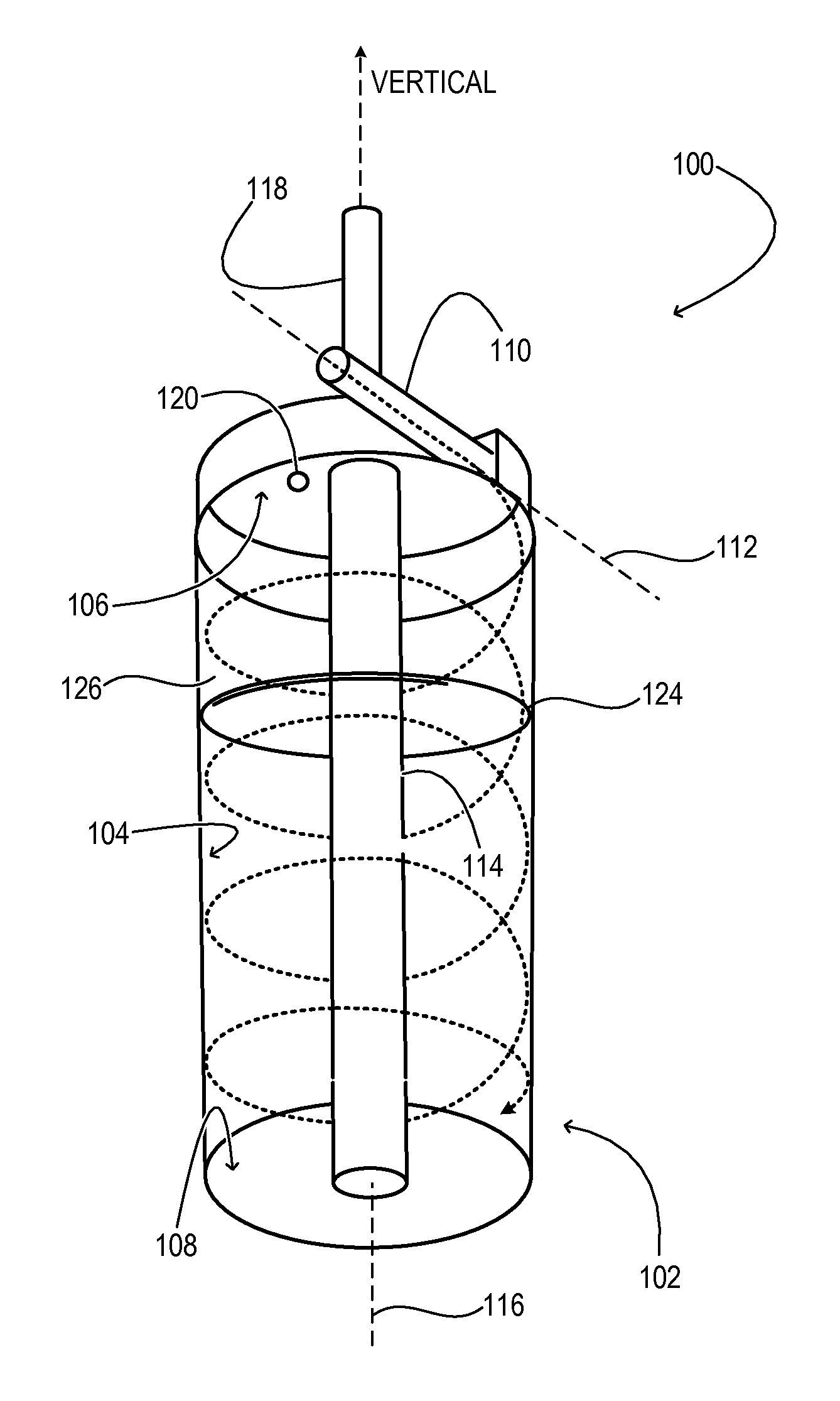
A fuel-air separator includes a chamber with an interior side-wall surface and adjacent interior top and bottom surfaces. An inlet of the fuel-air separator opens to the interior side-wall surface to admit fuel and air and to cause the fuel and air to flow helically down and along the interior side-wall surface. A diptube opens to the bottom surface and extends along an axis of the interior side-wall surface to a fuel outlet, while the separated air is released to the atmosphere.

Description

TECHNICAL FIELD[0001]This application relates to the field of motor vehicle engineering, and more particularly, to separating air from fuel in a motor-vehicle fuel system.BACKGROUND AND SUMMARY[0002]In a motor-vehicle fuel system with high-pressure fuel injection, air entrained in the fuel can have various undesirable effects. Such effects include engine hesitation and stalling, difficulty starting, and damage to the fuel-injection system. In the current state-of-the-art, entrained air may be separated from the fuel in fuel-pump and pressure-regulator componentry, and most commonly in the fuel-filter housing. The separated air may be admitted to a fuel-return line of the fuel-injection system, which takes it back to the fuel tank where it is vented to the atmosphere.[0003]The solution summarized above admits of several disadvantages. First, air present in the fuel-filter housing may limit the effective filtration area of the fuel filter, causing inadequate pressurization downstream ...

Claims


Application Information

Patent Timeline
Patent Type & Authority Patents(United States)
IPC IPC(8): B01D19/00F02M37/20B01D45/12B01D21/26F02M37/00B01D17/02B04C3/06
CPCF02M37/20B01D45/12B01D17/0217B01D19/0042B01D19/0057B01D21/267B04C3/06F02M37/0041
Inventor MYERS, ERICZHANG, YIALI, SYED K.DONG, MIKEARMESTO, CARLOS
Owner FORD GLOBAL TECH LLC
Learn More