
Bearing for structures

a technology for bearings and structures, applied in the direction of shock absorbers, machine supports, mechanical equipment, etc., can solve the problems of poor damping movement of bearings, high rigidity, and low durability of bearings, and achieve the effect of reducing large lateral displacements

Active Publication Date: 2011-05-05
DAMPTECH AS
View PDF6 Cites 2 Cited by
  • Summary
  • Abstract
  • Description
  • Claims
  • Application Information

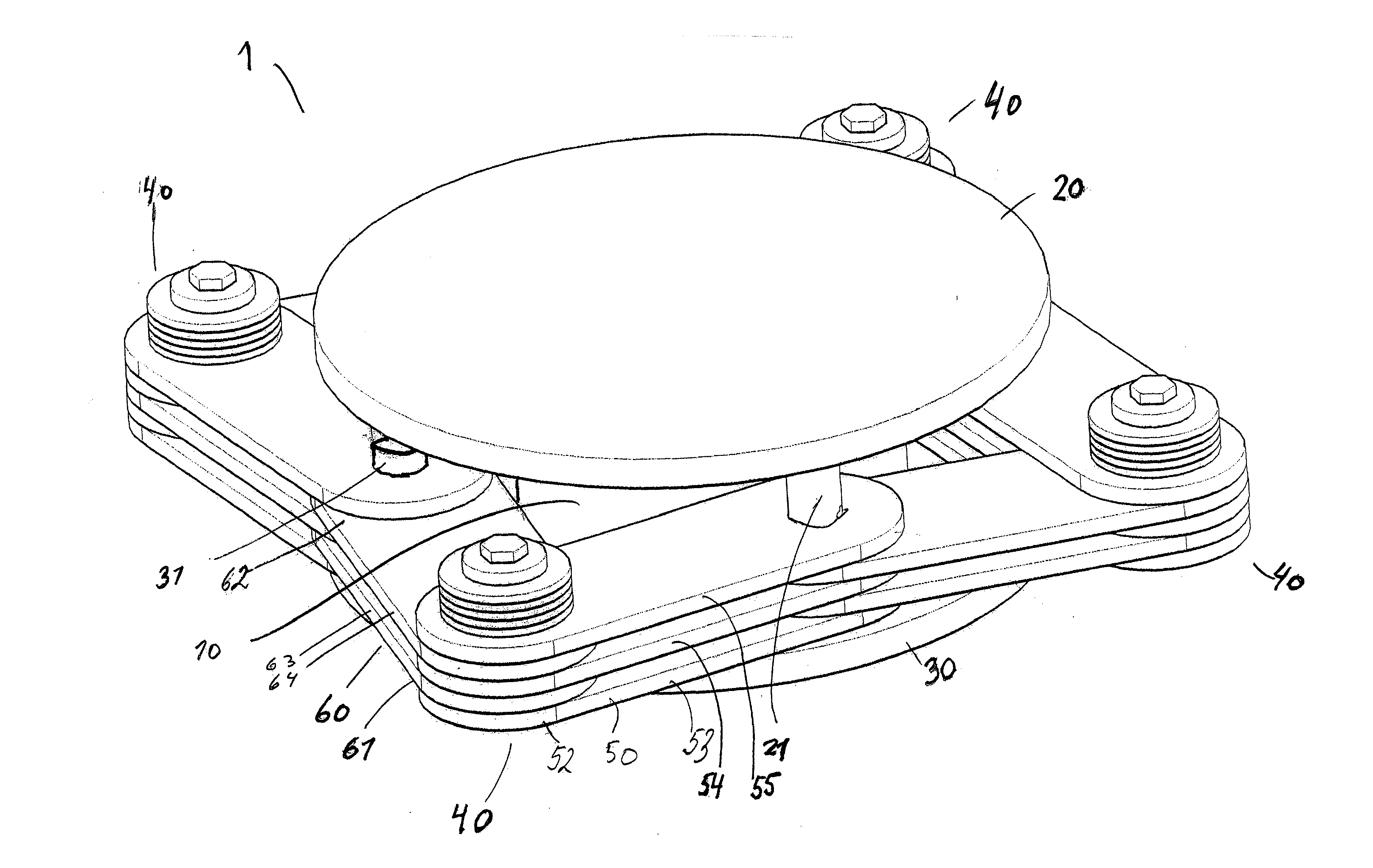
AI Technical Summary

Benefits of technology

[0004]It is an object of the invention to provide a bearing that will provide efficient dampening of movement between structural or non structural elements or parts of structures, such as buildings, bridges, elevated highways, and mechanical systems (e.g. machinery).
[0005]It is another object of the invention to provide a bearing providing dampening and allowing flexible movement between the structural or on structural elements or parts, between which the bearing may be mounted.
[0006]It is yet another object of the invention to provide a bearing providing dampening and allowing flexible movement between the structural or on structural elements or parts, between which the bearing may be mounted.
[0010]The invention is particularly, but not exclusively, advantageous for obtaining damping of the movements allowed by the bearing. While providing efficient damping it can handle large lateral displacements in a plane parallel to the plane defined by a fixture element, as well as large rotations. Further, the invention is particularly, but not exclusively, advantageous for obtaining high damping of the movements allowed by the bearing. The durability of the dampening of such large movements in the new type of bearing is largely improved to hundreds or thousands of oscillations, and thus the need for replacement during the lifetime of the structure in which the bearing is placed is eliminated or greatly reduced.
[0011]In an embodiment the rotational damping device of the bearing may comprise a first arm having oppositely arranged first and second ends; and a second arm having oppositely arranged first and second ends, said first arm being rotationally connected to the first fixture element at its first end, and rotationally connected to a first end of said second arm at its second end; said second arm further being rotationally connected to said second fixture element at a second end of the second arm. Thereby, an extremely flexible bearing is obtained with respect to allowing movement between structural parts to which the bearing may be connected, and yet allowing damping of the movements, even high damping of the movements.

Problems solved by technology

However, such bearings are poor in damping movements.
These, to a certain degree provide damping of the systems in which they are positioned, but are highly inflexible.
Experience has shown that e.g. the above mentioned lead enforced bearings are not very durable, and that they will wear or break down after only tens of “larger” amplitude vibrations / oscillations.
Since, such bearings are usually situated in structures for many years this is disadvantageous, since they may thus cause costly and technically cumbersome replacements.

Method used


Image

  • Bearing for structures
  • Bearing for structures
  • Bearing for structures

Examples


Embodiment Construction

[0028]In FIG. 1A-D is shown various prior art bearings 1′. FIG. 1A shows the general principle of a prior art bearing for building structures. Such a bearing typically comprises a block of a flexible material, e.g. rubber, and a fixture element 20, 30 at each side of the block 10. The block 10 consists in general of layers of rubber and may further comprise thin layers of steel plates 16 in between as shown in FIG. 1C. In some variants, a core of e.g. lead 15 may be provided, embedded in the block 10 of rubber, as shown in FIG. 1B. Alternatively, a steel spring (not shown) or the like may be provided embedded in the rubber block.

[0029]The fixture elements 20, 30 may be steel plates, and serve for connection of the bearing to e.g. constructional elements of a building. The fixture elements 20, 30 and the block 10 are fixedly connected.

[0030]Thus, as shown in FIG. 1, the bearing comprises two steel plates one on the top and one on the bottom of the block 10.

[0031]A variant, shown in F...


PUM


Abstract

A bearing (1) comprising a block (10) of flexible material, having two end surfaces (11, 12); and a first fixture element (20) and a second fixture element (30) connected at each of the end surfaces (11, 12); wherein at least one rotational damping device (40) is arranged between the first and second fixture elements (20, 30), the bearing thus providing high dampening between structural parts of a structure, such as buildings, bridges, elevated highways, and mechanical systems (machinery).

Description

FIELD OF THE INVENTION[0001]The present invention relates to a bearing for structures of the type including a block of flexible material, such as rubber, to be arranged between structural elements of the structure.BACKGROUND OF THE INVENTION[0002]In order to allow relative movement of structural parts of a structure, such as buildings, bridges, elevated highways, and mechanical systems (machinery), bearings, such as block rubber bearings, are used. The movement between the parts must be allowed, in order to prevent damages, since some or all the structural parts may themselves be influenced by, e.g. their use (e.g. mechanically induced oscillations), seismic activity or wind. An example of such bearings may be cylindrical blocks of rubber used to allow horizontal movement between the pillars of a bridge and the parts making up the deck of the bridge. Especially the deck is influenced by wind and oscillations created by vehicles moving on the deck, and must be allowed controlled move...

Claims


Application Information

Patent Timeline
IPC IPC(8): F16F15/02F16F13/04
CPCF16F13/04F16F7/04
Inventor MUALLA, IMAD
Owner DAMPTECH AS
Learn More