Introduction of ions into ion cyclotron resonance cells

a cyclotron resonance and ion technology, applied in the direction of electron/ion optical arrangement, tube electrostatic deflection, particle separator tube details, etc., can solve the problems of deteriorating the conditions for a clean measurement of the cyclotron frequency, increasing the intensity of the peak, and impairing the detection signal. , to achieve the effect of reducing the magnetron orbi

Active Publication Date: 2016-05-31
BRUKER DALTONIK GMBH & CO KG
View PDF6 Cites 5 Cited by
  • Summary
  • Abstract
  • Description
  • Claims
  • Application Information

AI Technical Summary

Benefits of technology

[0035]In a second embodiment, the gated DC voltages applied to mantle electrodes are adjusted such that the signal intensity of at least one even-numbered harmonic peak with the frequencies of 2nνR±mνM (with n=1, 2, 3, . . . and m=1, 2, 3, . . . ) becomes minimal. The signal intensity of at least one even-numbered harmonic peak with the frequencies of 2nνR±mνM (with n=1, 2, 3, . . . and m=1, 2, 3, . . . ) can also be reduced by varying a post capture delay time prior or after adjusting the gated DC voltages, e.g., with respect amplitude (height and variation in time) and duration (start and end point). Minimizing the signal intensity of even-numbered harmonic peaks results in a reduced magnetron orbit of ions captured in the ICR cell.

Problems solved by technology

Although the applied electric trapping field helps keeping the ions from escaping the ICR cell, it definitely deteriorates the conditions for a clean measurement of the cyclotron frequency.
Any distortion / asymmetry of the electric field or improper injection of an ion packet into the ICR cell, however, entails a magnetron motion of the ions in the ICR cell.
It also impairs the detected signal, leads to an increase of the intensity of the peaks associated with the even-numbered (e.g., second) harmonics in the Fourier transformed spectrum and to more abundant sidebands of the ion signal.
In extreme cases, ions can be lost during the cyclotron excitation when they are on large magnetron orbits that are critically close to the cylinder mantle electrodes.
Additionally, a large magnetron orbit can cause problems when using a so-called multiple frequency detection method.
However, this method can only be successfully applied if ions have no magnetron orbits or if they are vanishingly small.
Moderate or large magnetron orbits severely complicate the ICR mass spectra and reduce the signal intensity of the multiple-frequency mass peaks.
However, reducing the magnetron radius in dependence of the PCD time, which is in some cases quite long, restricts the operations of the FT-ICR mass spectrometer with fast pre-separation techniques, such as a liquid chromatographic separator.
Ions which are generated in external ion sources and which are electrostatically injected into the ICR cell, as the case may be exactly on the cell axis without velocity components perpendicular to the magnetic field, may not be successfully captured in the cell.
A more complex version of this method is the gas-assisted dynamic trapping of ions.
A pulse of collision gas (such as nitrogen or argon) is injected into the cell, which is commonly kept at ultrahigh vacuum, and takes off the excessive kinetic energy and thus reduces the cyclotron orbit size, however on the expense of increasing the magnetron orbit.
All methods using a pulsed gas have also the disadvantage that the mass spectrometric system is not ready to acquire a highly resolved mass spectrum until the additional gas is substantially pumped away.
The continuous application of the pulsed gas method has the further disadvantage of slowly increasing the background pressure.
The inverse leaf electrodes (57, 59, 66 and 68) are normally not used as detection electrodes since these are connected to DC voltage power supplies and thus lead to noisy ICR signals.

Method used


Image

  • Introduction of ions into ion cyclotron resonance cells
  • Introduction of ions into ion cyclotron resonance cells
  • Introduction of ions into ion cyclotron resonance cells

Examples


Embodiment Construction

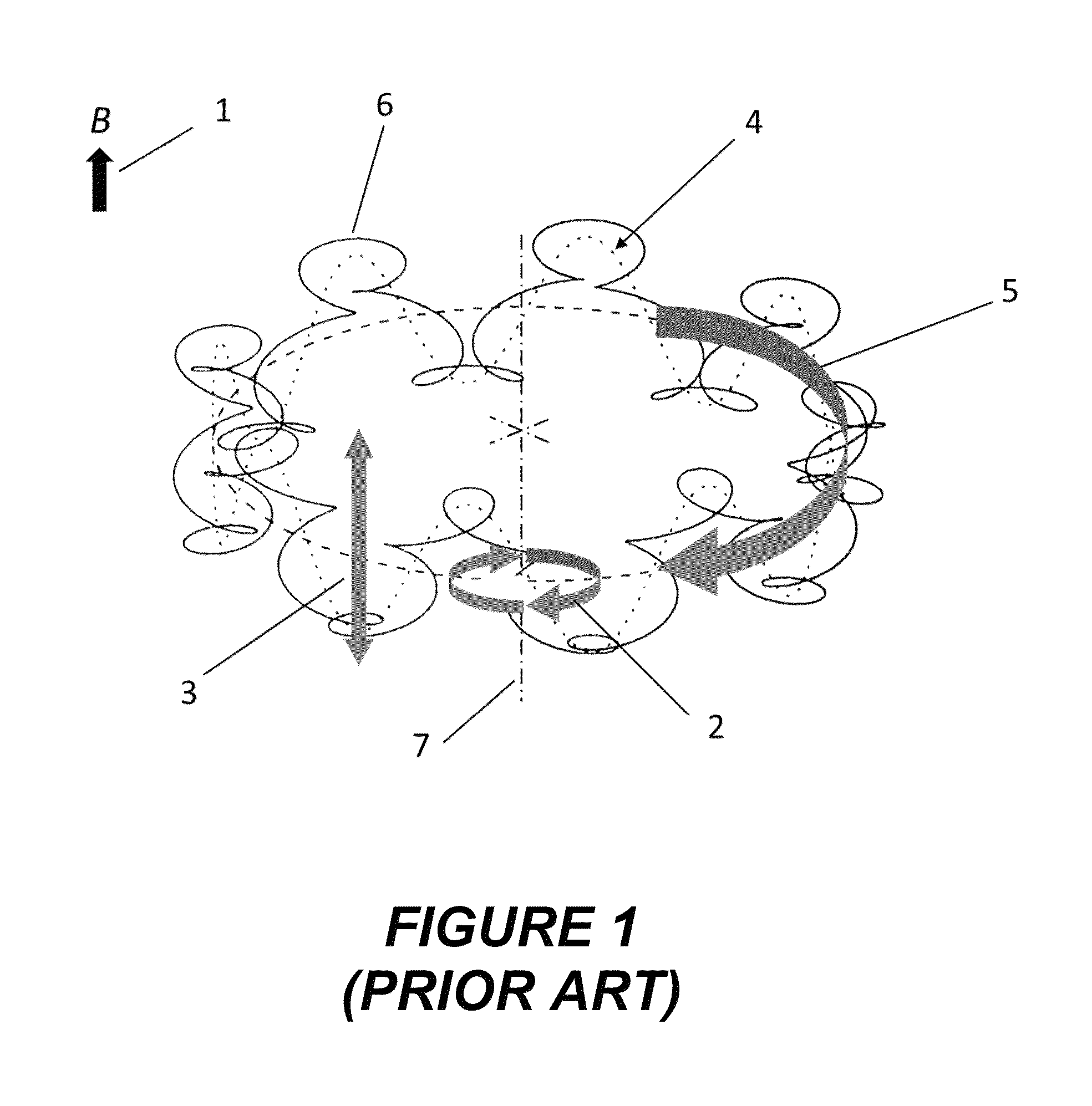
[0053]The present invention aims at reducing the initial magnetron orbit of ions captured in the ICR cell by deflecting the ions in the ICR cell during the injection period.

[0054]The existence of the magnetron motion in the ICR cell normally produces weak sidebands around the main ion cyclotron resonance signal of an ion measured at the frequency νR which are visible on the frequency scale in a distance of the magnetron frequency νM and 2νM. Additionally, in the mass spectrum a peak with half the mass, i.e., with the doubled reduced cyclotron frequency 2νR can appear when the magnetron orbit center is not the ICR cell axis center. This is the second harmonic peak, its abundance being directly related to the displacement of the magnetron orbit center and ICR cell axis. This can happen when the electric trapping field axis is shifted in respect to the ICR cell axis. Another signal with comparable abundance appears next to the 2νR signal, which is a satellite peak with a frequency of (...


PUM


Abstract

The invention relates to a method and a device for introducing ions into an ICR cell of Fourier transform ion cyclotron resonance mass spectrometers, in particular with a reduced the magnetron orbit. The invention is based on applying at least one gated DC voltage to a mantle electrode of the ICR cell prior to the excitation of the cyclotron motion such that injected ions are deflected inside the ICR cell in at least one radial direction.

Description

BACKGROUND OF THE INVENTION[0001]1. Field of the Invention[0002]The invention relates to methods and devices for introducing ions into a measuring cell of a Fourier transform ion cyclotron resonance mass spectrometer (FT-ICR MS), in particular for reducing the magnetron orbit of ions introduced into the ICR cell.[0003]2. Description of the Related Art[0004]In a magnetic field with the flux density B, an ion with the mass m, the elementary charge e and the charge number z performs a circular motion (cyclotron motion) in the radial plane perpendicular to the magnetic field lines with the well-known cyclotron frequency:[0005]vc=zeB2⁢π⁢⁢m(1)The cyclotron radius rc of an ion with the mass m, the elementary charge e, the charge number z, and the kinetic energy Ekin in a magnetic field of the flux density B is given by the following equation:[0006]rc=2⁢mEkinzeB(2)In the thermal energy range, e.g., at a temperature of 298 K, and in a magnetic field with the flux density of 7 Tesla, the cycl...

Claims


Application Information

Patent Timeline
Patent Type & Authority Patents(United States)
IPC IPC(8): H01J49/34H01J49/26H01J49/00H01J49/42H01J49/38H01J49/22H01J49/06
CPCH01J49/062H01J49/0031H01J49/22H01J49/26H01J49/38H01J49/426
Inventor BAYKUT, GOKHANJERTZ, ROLAND
Owner BRUKER DALTONIK GMBH & CO KG
Why Eureka
Try Eureka