Drive control device, electrical apparatus and drive control method

a technology of drive control and electrical equipment, applied in the direction of dynamo-electric converter control, dynamo-electric gear control, electric generator control, etc., can solve the problems of increasing the cost due to addition of configuration, inability to perform sufficient energy-saving operation, electrical equipment also facing this problem, etc., to achieve low capacity, low cost, and energy saving

Active Publication Date: 2016-05-10
MATSUI MFG
View PDF9 Cites 9 Cited by
  • Summary
  • Abstract
  • Description
  • Claims
  • Application Information

AI Technical Summary

Benefits of technology

[0029]As described above, if the electric motor is operated at a rotational frequency equal to or greater than the base rotational frequency, for controlling the rotational frequency of the rotating shaft of the electrical apparatus in accordance with the load state, the rotational frequency of the electric motor can be controlled in accordance with the load merely by comparing the magnitudes of the detected output power (physical amount) and the power threshold value. Therefore, for example, an inverter of a relatively low cost that outputs merely the output power of the electric motor can be used for controlling the rotational frequency of the electrical apparatus. Furthermore, since the value of a torque is changed in accordance with the rotational frequency in the constant output region of the electric motor, it is necessary to use different threshold values in accordance with the rotational frequency of the electric motor for the comparison of a detected torque value and a threshold value. Accordingly, for controlling the rotational frequency of the electric motor, it is necessary to calculate a threshold value in accordance with the rotational frequency, which increases the cost due to addition of a configuration for the calculation. Since the magnitudes of the detected output power (physical amount) and the power threshold value are compared, there is no need to calculate a threshold value for the torque, which reduces the cost, and thus, a simple configuration can be employed for controlling the rotational frequency of the electrical apparatus in accordance with the load characteristic.
[0048]According to the present invention, the rotational frequency of an electrical apparatus can be controlled in accordance with a load characteristic. Furthermore, an inexpensive electric motor with a low capacity can be used and energy can be saved.

Problems solved by technology

Therefore, a drive motor with a large capacity (a large rated value) is driven at a low load ratio, and this leads to a problem in which a sufficient energy-saving operation cannot be performed.
In addition, such a device dealing with a variety of loads is not limited to the crusher but applies to other electrical apparatuses used in industrial machinery, and such electrical apparatuses also face this problem.
Accordingly, for controlling the rotational frequency of the electric motor, it is necessary to calculate a threshold value in accordance with the rotational frequency, which increases the cost due to addition of a configuration for the calculation.
Therefore, if it is determined, as in the conventional technique, whether or not a grinding object can be crushed depending upon whether or not the torque of the electric motor falls in an allowable range, since an unexpectedly large torque is actually applied to the load, it is apprehended that the actual torque may exceed the allowable range.

Method used


Image

  • Drive control device, electrical apparatus and drive control method
  • Drive control device, electrical apparatus and drive control method
  • Drive control device, electrical apparatus and drive control method

Examples


embodiment 1

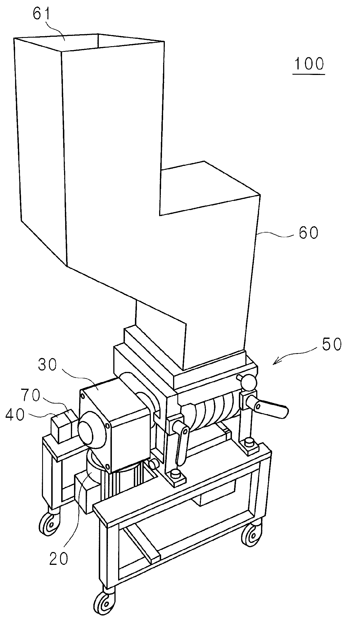
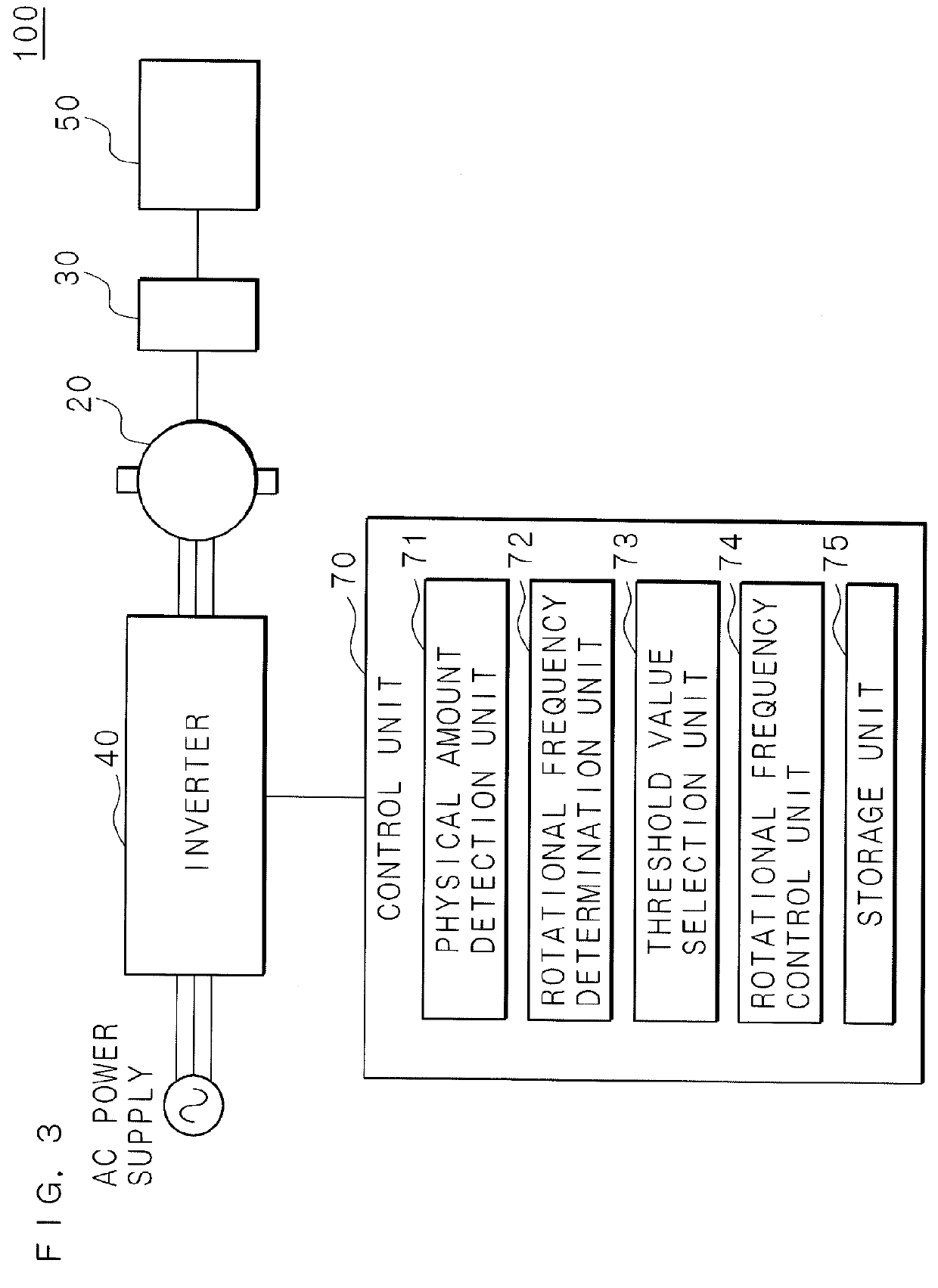
[0073]The present invention will now be described with reference to the accompanying drawings illustrating embodiments thereof. FIG. 1 is an appearance perspective view illustrating the outline of an installation example of a crusher 100 including a drive control device according to Embodiment 1. Herein, the crusher 100 will be described as an example of an electrical apparatus. It is noted that the electrical apparatus is not limited to the crusher 100. The crusher 100 includes: a crusher main body 50 equipped with a housing; an inverter 40 that converts the frequency (base frequency) of an AC power supply supplied from a commercial power supply of 50 Hz or 60 Hz and outputs an AC voltage of the converted frequency; a motor (electric motor) 20 driven by the AC voltage output from the inverter 40; a reduction gear 30 for reducing the rotational frequency of a motor shaft of the motor 20; a control unit 70 working as a drive control device for controlling the operation of the crusher...

embodiment 2

[0119]FIG. 9 is a block diagram of an example of a circuit configuration of a crusher 120 according to Embodiment 2. Differently from the crusher 100 of Embodiment 1, the crusher of this embodiment includes a torque threshold value calculation unit 76 instead of the rotational frequency determination unit 72 and the threshold value selection unit 73. Although the threshold value is selected in Embodiment 1, a torque threshold value is calculated in Embodiment 2.

[0120]A physical amount detection unit 71 detects a feature amount pertaining to the torque of a motor 20. The feature amount pertaining to the torque is, for example, a torque itself, a torque current, a load current or the like of the motor 20. If the torque current of the motor 20 or the load current of the electric motor is detected as the feature amount, the detected torque current or load current may be converted into a torque.

[0121]In operating the motor 20 at a frequency equal to or greater than the base rotational fr...

embodiment 3

[0149]FIG. 14 is a block diagram of an example of a circuit configuration of a crusher 140 according to Embodiment 3. Differently from the crusher 100 of Embodiment 1, the crusher of this embodiment includes a power threshold value calculation unit 77 instead of the rotational frequency determination unit 72 and the threshold value selection unit 73. While a threshold value is selected in the configuration of Embodiment 1, a power threshold value (an output power threshold value) of a motor 20 is calculated in the configuration of Embodiment 3.

[0150]A physical amount detection unit 71 detects an output power (output) of the motor 20.

[0151]If the motor 20 is operated at a rotational frequency equal to or lower than the base rotational frequency, a rotational frequency control unit 74 controls the rotational frequency of a rotating shaft of a crusher main body 50 in accordance with a magnitude relationship between the detected output power and a power threshold value.

[0152]The output ...


PUM


Abstract

A drive control device is provided with a physical amount detection unit which detects the physical amount pertaining to the output of a motor, a rotational frequency determination unit for determining whether the rotational frequency of the motor is equal to or greater than a base rotational frequency, a threshold value selection unit for selecting a threshold value for the physical amount in accordance with the determination result of the rotational frequency determination unit, and a rotational frequency control unit for controlling the rotational frequency of a rotating shaft in accordance with the magnitude relationship between the detected physical amount and the selected threshold value.

Description

CROSS-REFERENCE TO RELATED APPLICATIONS[0001]This application is the national phase under 35 U.S.C. §371 of PCT International Application No. PCT / JP2012 / 070953 which has an International filing date of Aug. 20, 2012 and designated the United States of America.BACKGROUND[0002]The present invention relates to a drive control device for controlling drive of an electrical apparatus including a rotor provided on a rotating shaft that is rotated by an electric motor driven by an inverter for converting a frequency of an AC power supply, an electrical apparatus including the drive control device, and a drive control method.DESCRIPTION OF RELATED ART[0003]In order to overcome problems of environmental pollution and increase of industrial wastes, it has been more and more significant to establish recycling-based society. For example, in a molding plant for manufacturing moldings or molded components by using synthetic resins represented by plastic, unwanted parts designated as sprue runners ...

Claims


Application Information

Patent Timeline
Patent Type & Authority Patents(United States)
IPC IPC(8): H02P23/00H02P27/00H02P25/00B02C18/24B02C18/14H02P27/04B02C4/42B02C4/10B02C4/08H02P21/00H02P21/02H02P21/22H02P23/02H02P23/07H02P27/06
CPCH02P23/0077B02C4/08B02C4/10B02C4/42B02C18/142B02C18/24H02P23/009H02P27/047
Inventor YAMASHITA, SAIJIHARU, MINORU
Owner MATSUI MFG
Why Eureka
Try Eureka