Printing apparatus

a printing apparatus and printing head technology, applied in the field of printing apparatuses, can solve the problems of inability to prevent contact between the counterparts of the contact panel, inability to print ink, and inability to prevent contact, so as to avoid damage to the print head, reduce the effect of structural space, and suitable design shap

Active Publication Date: 2016-05-03
FRANCOTYP POSTALIA
View PDF18 Cites 0 Cited by
  • Summary
  • Abstract
  • Description
  • Claims
  • Application Information

AI Technical Summary

Benefits of technology

[0012]A manual contact with the ink cartridge should be avoided entirely up to a point in time at the beginning of the process of removing the ink cartridge from the cartridge carrier, wherein this point in time is achieved only after a separation of the electrical connection from the contacts of the ink cartridge.
[0013]A spring force should not only be active to assist in the removal process of the ink cartridge, but also the effect of the spring force should also be limited and dimensioned so that the ink cartridge does not spring too far up out of the cartridge carrier before it can be grasped by a hand. It should be prevented that the upwardly moving ink cartridge strikes the opened hatch of the franking machine.
[0017]The locking lever has a first locking mechanism and a second locking mechanism, wherein the second locking mechanism is provided to lock the first locking mechanism. An actuator is provided to unlock the latch of the second locking mechanism. The lifting plate is arranged so as to be rotatable so far that the locking lever is held in an unlocked position after an ejection of an ink cartridge. Because the rotated lifting plate keeps the locking lever in an unlocked position, this prevents the projection from being unintentionally locked given an ejected ink cartridge. An unwanted unlocking of the first locking mechanism can similarly be prevented by the second locking mechanism.
[0019]An additional position is provided for sealing and servicing the ink cartridge. This additional position is achieved after the print carriage, with an ink cartridge inserted into the cartridge carrier, has been moved to a housing side wall and the print carriage is then rotated around an axis of the guide rod so that the cartridge carrier is tilted forward. Given a printing apparatus suitable for right-handed use, this is the right side wall of the housing within the printing apparatus viewed from the front. The release mechanism of the cartridge carrier tilted forward can then no longer be released via the actuator because, due to the rotation, the release mechanism and the actuator have been moved beyond the distance D that enables a release. Damage to the print head of the ink cartridge can advantageously be avoided since, in this position, the ink cartridge can neither be exchanged nor pushed too far into the cavity. It is thus avoided that a contact with the service station occurs and that the print head can be damaged.
[0021]The cartridge carrier has the following advantages and modes of operation.
[0022]The insertion movement of the ink cartridge during the insertion into the cartridge carrier is limited by one end of the connecting guide member on the inside of the side part on the sled side. This prevents the ink cartridge from being pushed too far into the cavity, and a cartridge carrier with very small structural shape can be realized.

Problems solved by technology

This device attached to the ink cartridge receptacle for the exchange of said ink cartridges is materially intensive and can lead to a contamination problem given a disadvantageous manual operation of the draw hooks, because the lower trailing edge of the nozzle surface of the ink cartridge rests on an elastic part that should prevent contact of the counterpart with the contact panel, but the clearance is so small that contact of the counterpart to the contact panel due to contamination therebetween cannot be precluded.
The contact problem results from the fact that the clearance is small and the elastic part and the contacts can be contaminated with ink upon removal of the ink cartridge, such ink having accumulated on the lower trailing edge during the printing.
The draw hook and the elaborate mechanism of the aforementioned prior art are disadvantageous to an easy exchange of the ink cartridges.
During the printing, the ink cartridge moves and therefore cannot be exchanged.
Given a small structural shape of the cartridge carrier with connecting guide member, a compression spring would be unsuitable in order to supply a force that would be necessary to convey the ink cartridge out of the cavity.
It is furthermore disadvantageous that the ink cartridge can also be manually exchanged when the cartridge carrier is rotated into a sealing position for the ink cartridge.
The print head could be damaged if, given manual operation, the ink cartridge is pushed in too far in order to press the locking edge of the ink cartridge past an edge at the opening of the cartridge carrier.
The print head of the ink cartridge could thereby be damaged given a contact with the service station.
All of this is disadvantageous given a manual handling of the ink cartridges.

Method used


Image

  • Printing apparatus
  • Printing apparatus
  • Printing apparatus

Examples


Embodiment Construction

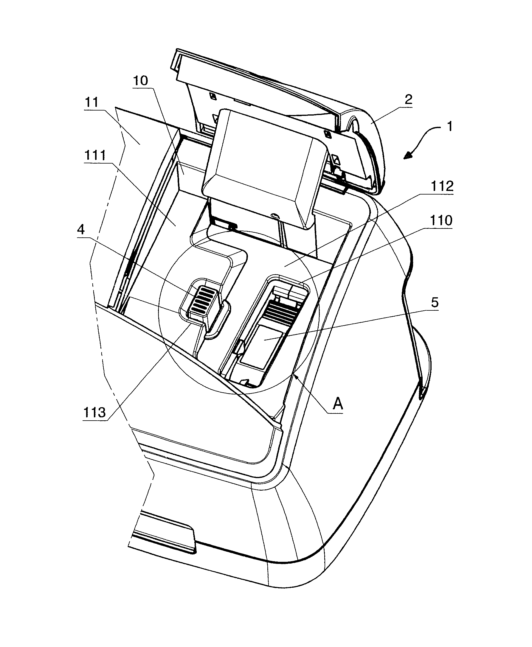
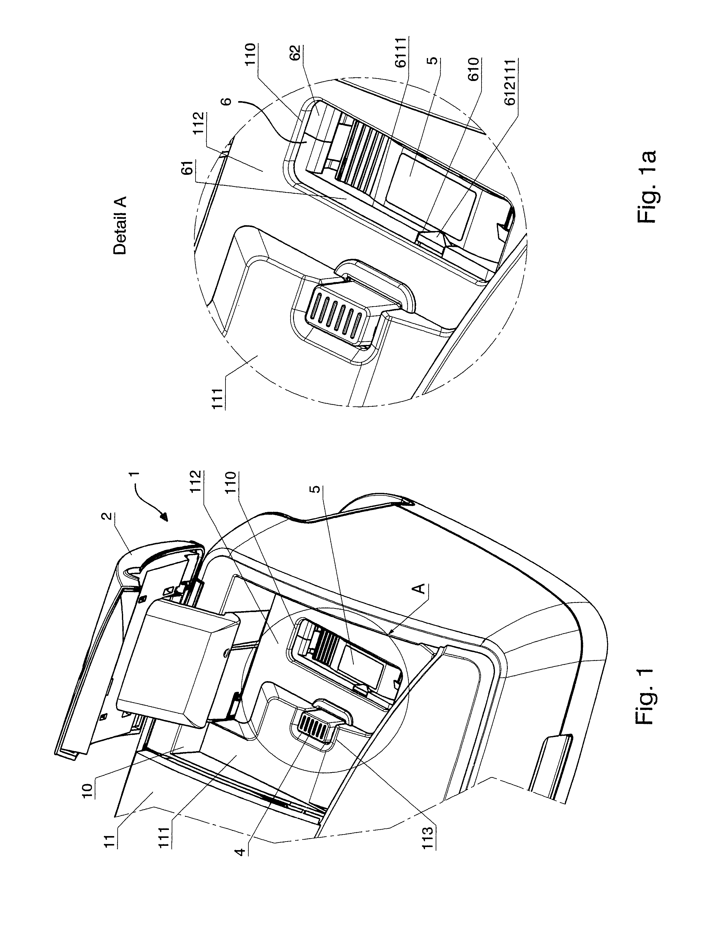
[0040]FIG. 1 shows a right half of a printing apparatus 1 with opened hatch 2 in a perspective view as seen from the top front right. A recess 10 is provided in the region which the hatch covers in the closed state. In this region, at a first level 111 under the top side of the upper housing part 11, the housing of the upper housing part 11 of the printing apparatus 1 extends further to the right, approximately to the middle of the opening 10, and then transitions into a second level 112. The second level 112 has a base in which a second window-like opening 110 is molded, for the exchange of the ink cartridge 5 inserted into a cartridge carrier. A third opening 113 in the base surface of the first level 111 is situated at the edge of the second level 112 of the upper housing part 11 of the printing apparatus 1. A cuboid actuator 4 projects upwardly out of the third opening 113. The upper edge of the cuboid actuator 4 is situated in line with the upper level edge and at approximately...


PUM


Abstract

A printing apparatus has a cartridge carrier and with a locking-and-ejection mechanism. The cartridge carrier has a cavity for insertion of an ink cartridge, and the locking-and-ejection mechanism is arranged on an outside of a side part of a cartridge carrier. This locking-and-ejection mechanism has a locking mechanism with a locking lever biased by a spring force produced by a first spring. The locking lever can be tilted around a rotation axis situated on the outside of the side part. The locking-and-ejection mechanism also has an ejection mechanism with a lifting plate biased by a spring force produced at least by a second spring. The lifting plate is rotatable on the outside of the side part, and the rotation axis of the lifting plate is stationary on the outside of the side part. The locking lever has a first locking mechanism and a second locking mechanism to the lock the first locking mechanism, and an actuator is operable to unlock the locking of the second locking mechanism. The lifting plate is rotatable by a sufficient amount that the locking lever is held in the unlocked position after an ejection of an ink cartridge.

Description

BACKGROUND OF THE INVENTION[0001]1. Field of the Invention[0002]The invention concerns a printing apparatus of the type having an inkjet printing device with an ink cartridge plugged into a cartridge carrier, and a control unit that controls the printing. The cartridge carrier is mounted on a sled that is moved back and forth during the printing. The sled can be controlled into a predetermined position to exchange the ink cartridge. The inserted ink cartridge is locked and can be unlocked and ejected via a mechanism installed on the side of the cartridge carrier. The printing apparatus is suitable for 1-inch receipt printers and is used in franking and addressing machines, and in other printing mail processing apparatuses.[0003]2. Description of the Prior Art[0004]An arrangement for exchanging ink cartridges is known from German Patent Application DE 102007060733 A1. This printing apparatus has a transport device for flat goods, a contact pressure device and a printing module, where...

Claims


Application Information

Patent Timeline
Patent Type & Authority Patents(United States)
IPC IPC(8): B41J2/175
CPCB41J2/1752B41J2/17503
Inventor MUHL, WOLFGANGBECKMANN, STEFAN
Owner FRANCOTYP POSTALIA
Why Eureka
Try Eureka