
Multiple technologies composite scintillation detector device

a detector device and composite technology, applied in the field of scintillation detector devices, can solve the problem that the backscattering detector is insufficient for effective detection, and achieve the effect of converting more effectively a light signal into an electrical signal

Active Publication Date: 2016-04-26
NUCTECH CO LTD +1
View PDF3 Cites 0 Cited by
  • Summary
  • Abstract
  • Description
  • Claims
  • Application Information

AI Technical Summary

Benefits of technology

[0010]Another object of the present invention is to provide a backscattering scintillation detector device, which can more effectively detect radiation and can transmit and convert more effectively a light signal into an electrical signal.

Problems solved by technology

However, the conventional backscattering detector is insufficient for effective detection for X-ray, light collection and light conversion, which becomes a bottleneck of improvement of detection performance of a backscattering detecting device.

Method used


Image

  • Multiple technologies composite scintillation detector device
  • Multiple technologies composite scintillation detector device
  • Multiple technologies composite scintillation detector device

Examples


Embodiment Construction

[0035]Technical solutions of the present invention will be described hereinafter in more detail by the way of embodiment with reference to figures of the attached drawings, wherein the same or like reference numerals refer to the same or like elements throughout the specification. The explanation of the embodiment of the present invention with referring to the accompanying drawings is intended to expound the general inventive concept of the present invention, rather than being construed as limiting to the present invention.

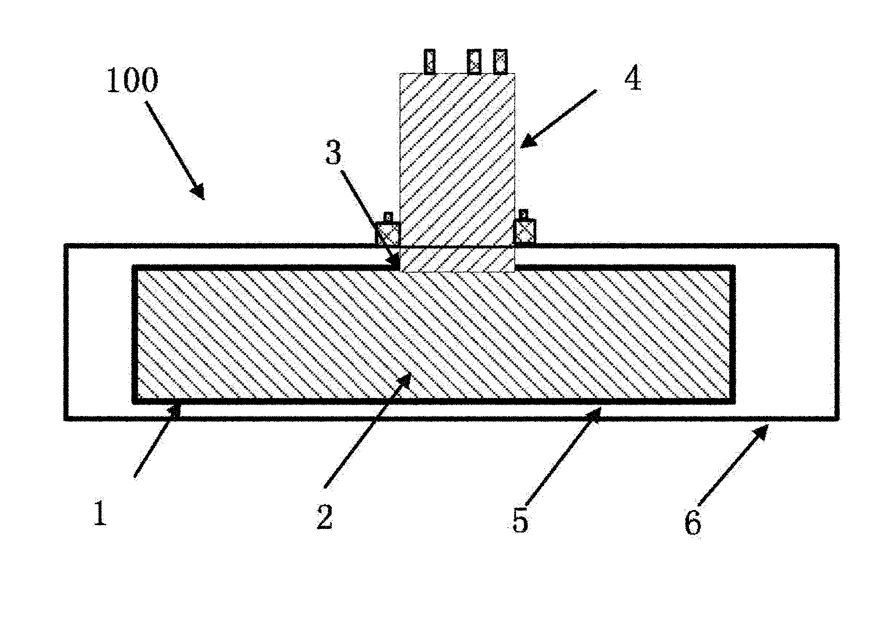
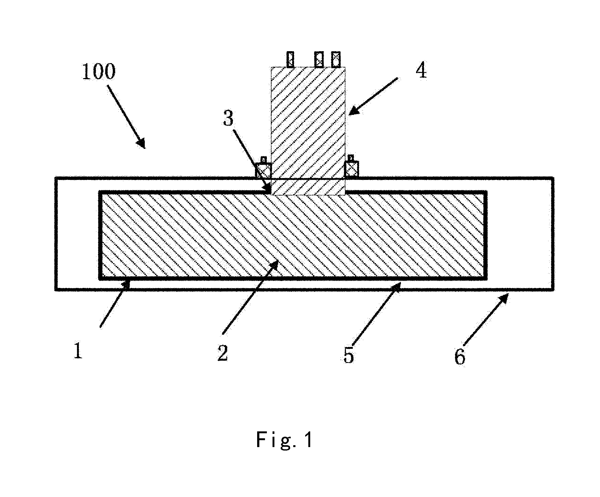
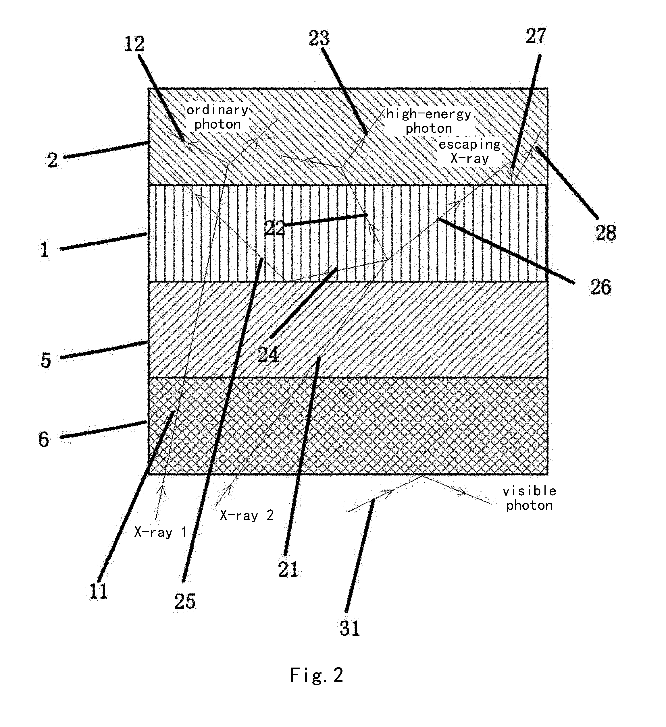
[0036]Referring to FIG. 1, a backscattering scintillation detector device 100 according to an embodiment of the present invention is illustrated. The backscattering scintillation detector device 100 comprises a scintillation crystal detector 2, a X-ray sensitizing screen 1, which is disposed forward the scintillation crystal detector 2 and where a backscattered X-ray from an object to be detected is processed by the X-ray sensitizing screen 1 and then at least par...


PUM


Abstract

The invention presents a backscattering scintillation detector. The scintillation detector includes a scintillation crystal detector; a X-ray sensitizing screen, which is disposed forward the scintillation crystal detector and where a backscattered X-ray from an object to be detected is processed and then at least part of the processed X-ray is incident to scintillation crystal detector; and photoelectric multiplier, which is disposed backward the scintillation crystal detector and is configured to collect a light signal from scintillation crystal detector and convert it to an electrical signal. Through the above preferable embodiment, a X-ray sensitizing screen, a scintillation crystal detector, and light guiding and wave-drifting technologies are combined together to obtain a novel scintillation detector, which can improve detection of X-ray, transmission of light signal and conversion of light signal to electrical signal.

Description

CROSS-REFERENCE TO RELATED APPLICATIONS[0001]This application claims the benefit of Chinese patent application No. 201310746145.1, filed on Dec. 30, 2013 with State Intellectual Property Office of China, and the inventions of which are incorporated herein in its entirety by reference.BACKGROUND OF THE INVENTION[0002]1. Field of the Invention[0003]The present invention relates to a scintillation detector device, and particularly, to a backscattering scintillation detector device which involves multiple technologies and can be applied in security inspection for, such as, human body, vehicle, etc.[0004]2. Description of the Related Art[0005]X-ray backscattering imaging technology is one of the main technology in field of security inspection for human body or vehicle. Through scanning human body or vehicle by X-ray while receiving X-ray backscattering signal by using a large-size backscattering detector, a backscattering image by X-ray of an object being scattered can be obtained by col...

Claims


Application Information

Patent Timeline
Patent Type & Authority Patents(United States)
IPC IPC(8): G01T1/20
CPCG01T1/2002G01T1/2008
Inventor ZHAO, ZIRANCHEN, ZHIQIANGLI, YUANJINGWU, WANLONGLIU, YINONGRUAN, MINGJIN, YINGKANGTANG, LE
Owner NUCTECH CO LTD
Learn More