
Method and system for knock control

a technology of knock control and control fluid, which is applied in the direction of electric control, combustion engines, machines/engines, etc., can solve the problems of reducing the cooling effect the temperature of the knock control fluid, and the insufficient knock relief of the pulse width calculated based on the nominal value, so as to reduce the exhaust emissions and reduce the price of conventional fuels.

Active Publication Date: 2016-04-26
FORD GLOBAL TECH LLC
View PDF9 Cites 6 Cited by
  • Summary
  • Abstract
  • Description
  • Claims
  • Application Information

AI Technical Summary

Benefits of technology

[0002]Alternate fuels have been developed to mitigate the rising prices of conventional fuels and for reducing exhaust emissions. For example, alcohol and alcohol-based fuel blends have been recognized as attractive alternative fuels, in particular for automotive applications. Various engine systems may be used with alcohol fuels, utilizing various engine technologies and injection technologies. Further, various approaches may be used to control such alcohol-fuelled engines to take advantage of the charge-cooling effect of the high octane alcohol fuel, in particular to address engine knocking.
[0008]In this way, a knock control fluid mass can be adjusted by adjusting injection settings of a knock control fluid in anticipation of changes in knock relieving efficiency due to heating of the knock control fluid at a time of release from an injector. By estimating an expected temperature of the fluid at the time of release based on injector conditions, such as based on whether the injector was already activated or idle, a drop in the charge cooling effect of the knock control fluid can be predicted, and knock relief compensating adjustments may be appropriately made. By increasing the pulse width of direct injection of the knock control fluid at elevated injector temperatures, a knock relieving efficiency of the fluid at release can be improved. In addition, injector fouling and thermal degradation can be reduced. By better addressing engine knock, engine performance can be improved.

Problems solved by technology

However, the inventors herein have identified potential issues with such an approach.
Consequently, when use of a knock control fluid is resumed (after a period of not using the injector), a pulse width calculated based on the nominal values may not provide sufficient knock relief due to potentially reduced mass flow and reduced charge cooling.
This may cause a temperature of the knock control fluid, at a time of release from the direct injector, to also increase, and a charge cooling effect of the knock control fluid to decrease.

Method used


Image

  • Method and system for knock control
  • Method and system for knock control
  • Method and system for knock control

Examples


Embodiment Construction

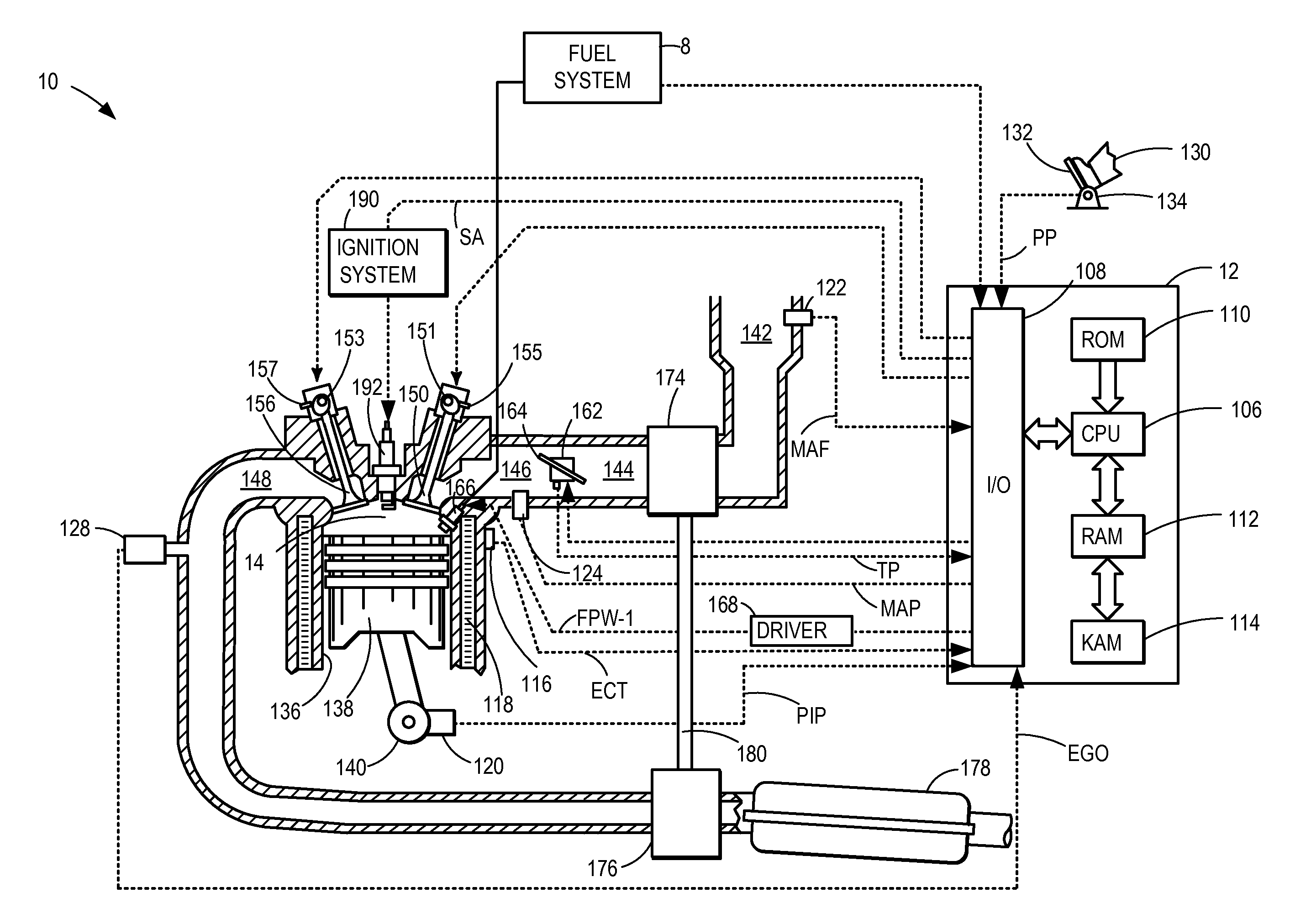
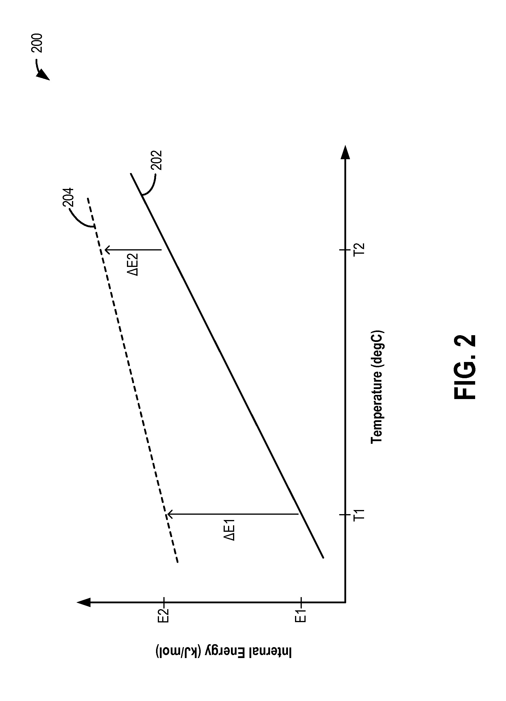
[0016]Methods and systems are provided for improving knock control in an engine, such as the engine of FIG. 1. Injection settings for direct injection of a knock control fluid may be adjusted based on an estimated temperature of the fluid at a time of release to compensate for changes in charge cooling efficiency of the fluid at elevated temperatures (FIG. 2). A controller may be configured to perform a control routine, such as the example routine of FIG. 3, to determine initial setting for direct injection of a knock control fluid based on a likelihood of knock and nominal conditions of the fluid. The controller may then predict a temperature of the knock control fluid at a time of release from the direct injector based on injector conditions such as whether the injector is already activated or deactivated, a temperature of the injector, heat transfer from the injector to the fluid, etc. In response to the prediction of an elevated knock control fluid temperature at a time of relea...


PUM


Abstract

Methods and systems are provided for improving engine knock control by accounting for a drop in charge cooling efficiency of a knock control fluid at higher temperatures. In response to the prediction of an elevated temperature of a knock control fluid at a time of release from a direct injector, a pulse width of the injection is adjusted. Any knock relief deficits are compensated for using alternate engine adjustments, such as boost or spark timing adjustments.

Description

FIELD[0001]The present application relates to methods and systems for using a knock control fluid for controlling knock in an internal combustion engine.BACKGROUND AND SUMMARY[0002]Alternate fuels have been developed to mitigate the rising prices of conventional fuels and for reducing exhaust emissions. For example, alcohol and alcohol-based fuel blends have been recognized as attractive alternative fuels, in particular for automotive applications. Various engine systems may be used with alcohol fuels, utilizing various engine technologies and injection technologies. Further, various approaches may be used to control such alcohol-fuelled engines to take advantage of the charge-cooling effect of the high octane alcohol fuel, in particular to address engine knocking.[0003]For example, in engines configured with a direct injector for delivering fuel or an alternate knock control fluid to engine cylinders, a pulse width of the direct injection may be adjusted to meet the knock control g...

Claims


Application Information

Patent Timeline
Patent Type & Authority Patents(United States)
IPC IPC(8): F02D19/12F02D19/06F02D41/30F02D41/00F02D19/08F02B75/12F02D13/02F02D41/38F02D35/02
CPCF02D19/0631F02D19/061F02D19/0689F02D19/084F02D41/0025F02D41/3094F02D13/0219F02B2075/125F02D19/12F02D35/027F02D2041/389F02D2200/0608F02D2200/0612Y02T10/36Y02T10/123Y02T10/12Y02T10/30F02B75/12F02D41/26
Inventor VANDERWEGE, BRAD ALANSHELBY, MICHAEL HOWARD
Owner FORD GLOBAL TECH LLC
Learn More