Complex circuit element and capacitor utilizing CMOS compatible antiferroelectric high-k materials

a technology of complex circuit elements and capacitors, applied in the field of integrated circuits, can solve the problems of dielectric breakdown, limited electrode distance, and limited capacitance of integrated planar mis/mim capacitors

Active Publication Date: 2016-04-19
GLOBALFOUNDRIES US INC
View PDF15 Cites 6 Cited by
  • Summary
  • Abstract
  • Description
  • Claims
  • Application Information

AI Technical Summary

Problems solved by technology

At present, the capacitance of integrated planar MIS / MIM capacitors is limited to 20 fF / μm2 because of constraints imposed by the available chip area and materials to be used as dielectrics in advanced capacitors.
The latter constraints arise from contamination issues present in CMOS technologies which restrict dielectrics used in MIS / MIM capacitors of advanced ICs to be compatible with the CMOS technology.
However, in advanced ICs, decreasing the distance between the electrodes is limited due to the appearance of leakage currents with decreasing thickness of the dielectric.
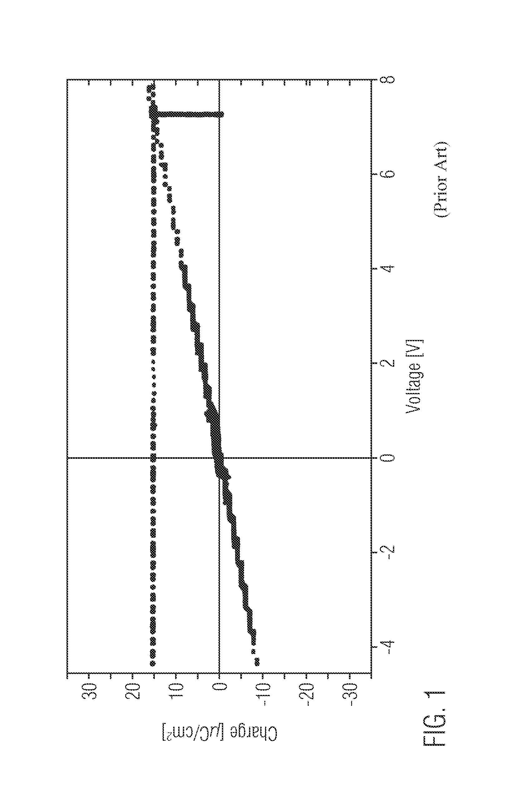
As indicated in FIG. 1, a required high target load of, for example, 15 μC / cm2 involves a high voltage drop across the capacitor, in the given example about 7 V, possibly causing dielectric breakdown and, therefore, posing a risk to the reliability of the whole IC comprising the capacitor.
Although ferroelectric and antiferroelectric dielectrics are generally known to have high dielectric constants or k-values, implementations, particularly of antiferroelectric dielectrics, raise new issues when considering concrete applications in advanced semiconductor fabrication.
For example, typical antiferroelectric films have a thickness of several 100 nm, and conventional antiferroelectric materials like perovskites, e.g., PZT, BaTiO3 and SBT, are not compatible with semiconductor manufacturing environments as contaminations are introduced, possibly causing yield losses in semiconductor fabrication plants.

Method used


Image

  • Complex circuit element and capacitor utilizing CMOS compatible antiferroelectric high-k materials
  • Complex circuit element and capacitor utilizing CMOS compatible antiferroelectric high-k materials
  • Complex circuit element and capacitor utilizing CMOS compatible antiferroelectric high-k materials

Examples


Embodiment Construction

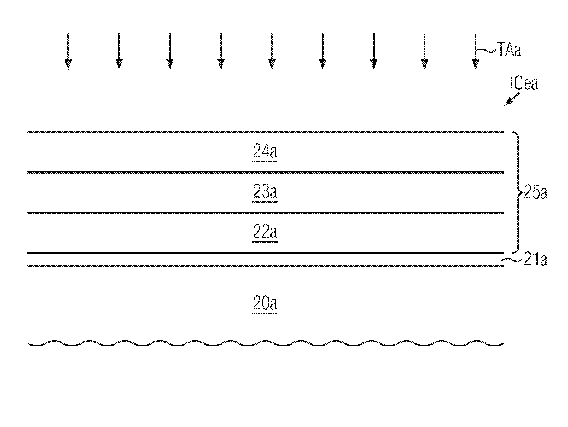
[0028]Various illustrative embodiments of the invention are described below. In the interest of clarity, not all features of an actual implementation are described in this specification. It will of course be appreciated that in the development of any such actual embodiment, numerous implementation-specific decisions must be made to achieve the developers' specific goals, such as compliance with system-related and business-related constraints, which will vary from one implementation to another. Moreover, it will be appreciated that such a development effort might be complex and time-consuming, but would nevertheless be a routine undertaking for those of ordinary skill in the art having the benefit of this disclosure.

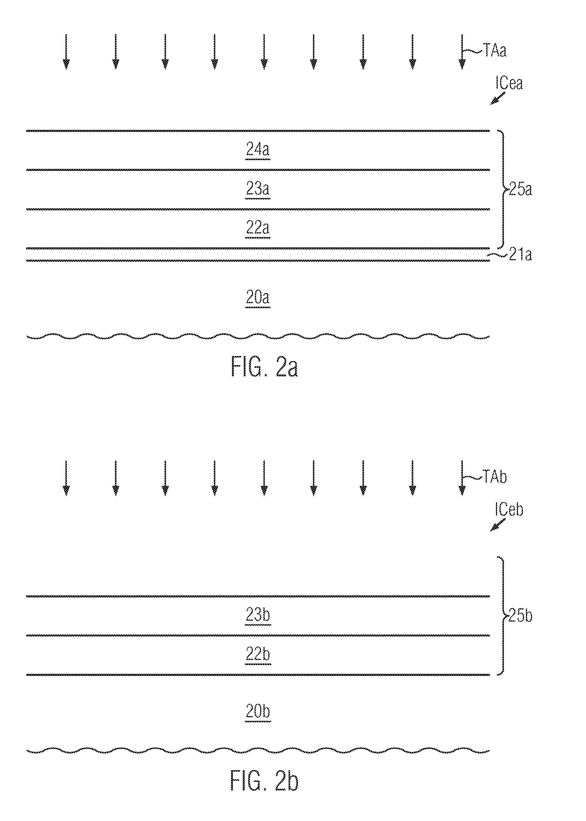
[0029]The present disclosure will now be described with reference to the attached figures.

[0030]Various structures, systems and devices are schematically depicted in the drawings for purposes of explanation only and so as to not obscure the present disclosure with details...


PUM


Abstract

The present disclosure provides integrated circuit elements and MIM / MIS capacitors having high capacitance and methods of forming according integrated circuit elements and integrated MIM / MIS capacitors and methods of controlling an integrated circuit element and an integrated MIM / MIS capacitor. In various aspects, a substrate is provided and a dielectric layer or insulating layer is formed over the substrate. Furthermore, an electrode layer is disposed over the dielectric layer or insulating layer. Herein, the dielectric layer or insulating layer is in an antiferroelectric phase. In various illustrative embodiments, the integrated circuit element may implement a MOSFET structure or a capacitor structure.

Description

BACKGROUND OF THE INVENTION[0001]1. Field of the Invention[0002]The present disclosure generally relates to integrated circuits, and, more particularly, to circuit elements and capacitors engineered in accordance with advanced CMOS techniques in which antiferroelectric high-k materials are applied.[0003]2. Description of the Related Art[0004]In modern electronic equipment, integrated circuits (ICs) experience a vast applicability in a continuously spreading range of applications. Particularly, the demand for increasing mobility of electronic devices at high performance and low energy consumption drives developments to more and more compact devices having features with sizes ranging even into the deep sub-micron regime, the more so as current semiconductor technologies are apt of producing structures with dimensions in the magnitude of 10 nm. With ICs representing a set of electronic circuit elements integrated on a semiconductor material, normally silicon, ICs can be made much small...

Claims


Application Information

Patent Timeline
Patent Type & Authority Patents(United States)
IPC IPC(8): H01L21/02H01L29/94H01L29/66H01L21/28
CPCH01L21/02189H01L21/02194H01L21/02107H01L21/0228H01L21/02181H01L21/28194H01L29/66181H01L29/94
Inventor MUELLER, JOHANNESTRIYOSO, DINA H.NOLAN, MARK GERARDWEINREICH, WENKESEIDEL, KONRADPOLAKOWSKI, PATRICK
Owner GLOBALFOUNDRIES US INC
Why Eureka
Try Eureka