
Battery power supply device and method of controlling power of the same

a battery power supply device and power supply technology, applied in the direction of emergency power supply arrangement, dc source parallel operation, ac network load balancing, etc., can solve the problem of power quality problem, inconvenient maintenance of switches, and limit the power supply that the battery power supply device can supply to the load, so as to prevent backward flow of battery energy to the external power source, simplify the circuit, and reduce the cost

Active Publication Date: 2016-04-05
TS NEXGEN CO LTD
View PDF22 Cites 2 Cited by
  • Summary
  • Abstract
  • Description
  • Claims
  • Application Information

AI Technical Summary

Benefits of technology

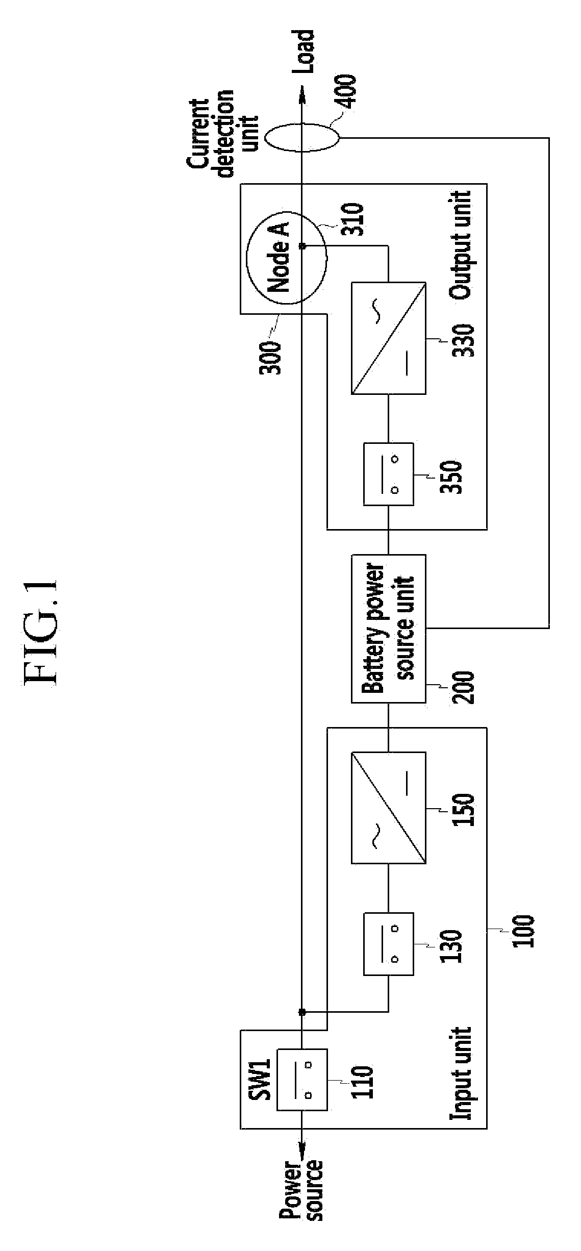
[0014]According to an exemplary embodiment of the present invention, by directly connecting a battery power supply device to an external power source without a power static switch, a circuit can be simplified and cost can be reduced.
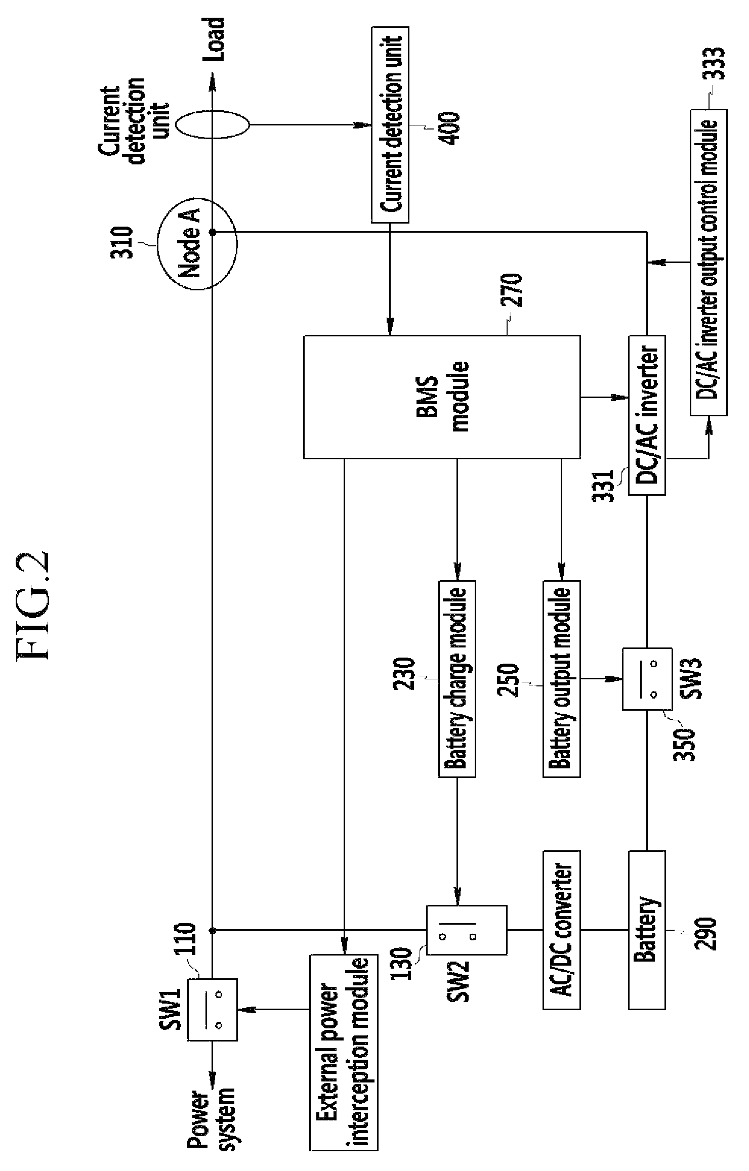
[0015]Further, by detecting a current that is supplied to a load using a current detection sensor, an output of an inverter is controlled, and thus a battery power supply device provides only a portion of power that the load requires and the external power source supplies the remaining power. Therefore, a problem occurring due to a limitation of an inverter capacity can be solved, and even if an overload is applied, energy that is stored in the battery can be supplied to the load without an instantaneous power failure, and backward flow of battery energy to the external power source can be prevented.
[0016]Further, by storing new reproduction energy, such as, particularly, that from sunlight and wind force at a battery, and connecting stored energy to the external power source with a method that can supply and use energy that is stored at the battery regardless of a magnitude of energy that is stored at the battery or capacity of an inverter, a power peak can be effectively managed.

Problems solved by technology

However, there is a limitation in power that the battery power supply device can supply to the load due to an output limitation of a battery inverter.
That is, as an instantaneous power failure occurs at a power conversion time point, so a problem of power quality occurs.
Further, by using the power static switch, a circuit is complicated, and the switch is consumption goods and thus it is inconvenient to regularly perform maintenance of the switch.

Method used


Image

  • Battery power supply device and method of controlling power of the same
  • Battery power supply device and method of controlling power of the same
  • Battery power supply device and method of controlling power of the same

Examples


Embodiment Construction

[0021]In the following detailed description, only certain exemplary embodiments of the present invention have been shown and described, simply by way of illustration. As those skilled in the art would realize, the described embodiments may be modified in various different ways, all without departing from the spirit or scope of the present invention. Accordingly, the drawings and description are to be regarded as illustrative in nature and not restrictive. Like reference numerals designate like elements throughout the specification.

[0022]In addition, in the entire specification, unless explicitly described to the contrary, the word “comprise” and variations such as “comprises” or “comprising” will be understood to imply the inclusion of stated elements but not the exclusion of any other elements.

[0023]In addition, the terms “-er”, “-or”, and “module” described in the specification mean units for processing at least one function and operation and can be implemented by hardware compone...


PUM


Abstract

A battery power supply device is provided. The battery power supply device includes: an input unit that receives external power; a battery power unit that is connected to the input unit to charge a battery with the external power; a current detection unit that detects a current that is supplied to a load and that provides the current to the battery power unit; and an output unit that provides the external power and battery power from one node to the load and that receives a load current from the battery power unit to adjust output of the battery power.

Description

CROSS REFERENCE TO RELATED APPLICATIONS[0001]This application is a national stage application under 35 U.S.C. 371 and claims the benefit of PCT Application No. PCT / KR2011 / 004673 having an international filing date of Jun. 27, 2011, which designated the United States, which PCT application claimed the benefit of Korean Patent Application No. 10-2010-0064475 filed Jul. 5, 2010, and Korean Patent Application No. 10-2011-0061329 filed on Jun. 23, 2011, the disclosures of each of which are incorporated herein by reference.BACKGROUND OF THE INVENTION[0002](a) Field of the Invention[0003]The present invention relates to a battery power supply device and a method of controlling power of the same.[0004](b) Description of the Related Art[0005]When an overload is applied or all energy that is stored in a battery is spent, a battery power supply device such as a conventional uninterruptable power supply (UPS) converts a power supply source that supplies power to a load from a battery to an exte...

Claims


Application Information

Patent Timeline
Patent Type & Authority Patents(United States)
IPC IPC(8): H02J3/00H02J3/32
CPCH02J3/00H02J3/32Y10T307/344H02J7/00H02J13/00
Inventor JUNG, EUN-EY
Owner TS NEXGEN CO LTD
Learn More