
Thermally assisted recording head utilizing laser light with limited wavelength range

a technology of laser light and recording head, which is applied in the direction of recording information storage, maintaining the carrier alignment of the head, instruments, etc., can solve the problems of insufficient reliability, low conversion efficiency, and difficult recording information with the conventional magnetic head, so as to suppress the temperature rise of the near-field light generator, the effect of increasing the temperature ris

Active Publication Date: 2016-04-05
TDK CORPARATION
View PDF15 Cites 0 Cited by
  • Summary
  • Abstract
  • Description
  • Claims
  • Application Information

AI Technical Summary

Benefits of technology

The patent text discusses the limitations of using a photodiode made from silicon (Si PD) for detecting laser light. The text explains that while using a Si PD is cost-effective, it can only detect light wavelengths between 1,000 nm and 1,500 nm. This is because the Si PD has a limited ability to cool down the laser light. However, the text also notes that using laser light with a wavelength between 890 nm and 1,000 nm can help to reduce the temperature rise of the near-field light generator, which is important for effective recording. Therefore, the technical effect of this patent is to provide a thermally assisted recording magnetic head that has reduced cost and is less likely to overheat the near-field light generator.

Problems solved by technology

However, the big anisotropic energy of the magnetic nanoparticle increases the coercive force of the magnetic recording medium and makes recording the information with the conventional magnetic head difficult.
But because the greater part of the energy of the irradiated light is reflected in the surface or converted into heat energy, the conversion efficiency is low.
Therefore, the plasmon antenna is prone to produce diffusion, cohesion, fusion and does not have enough reliability.
The thermally assisted magnetic recording head is more disadvantageous in a cost view than the conventional magnetic recording head without the heating means to a magnetic recording medium.

Method used


Image

  • Thermally assisted recording head utilizing laser light with limited wavelength range
  • Thermally assisted recording head utilizing laser light with limited wavelength range
  • Thermally assisted recording head utilizing laser light with limited wavelength range

Examples


Embodiment Construction

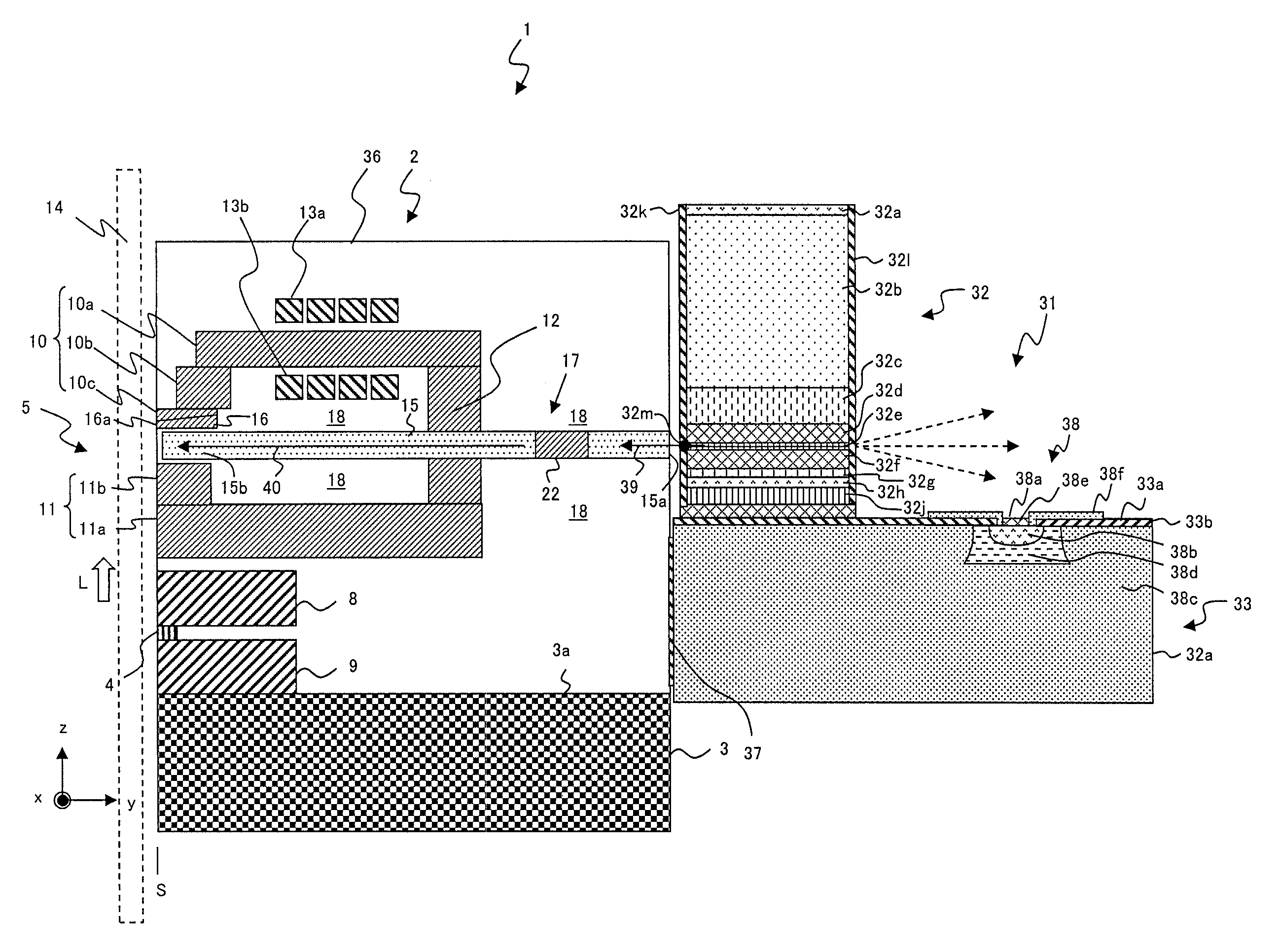
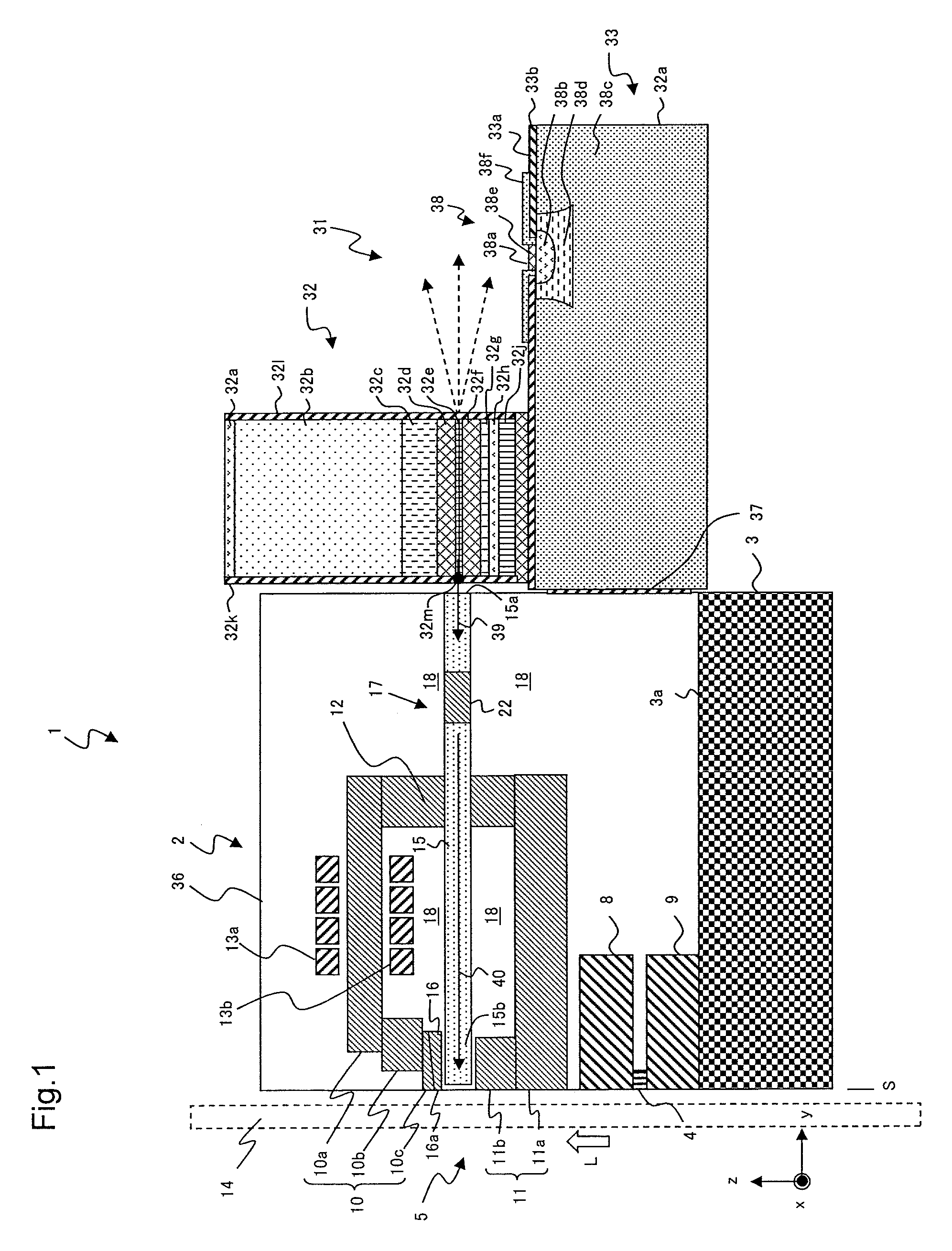
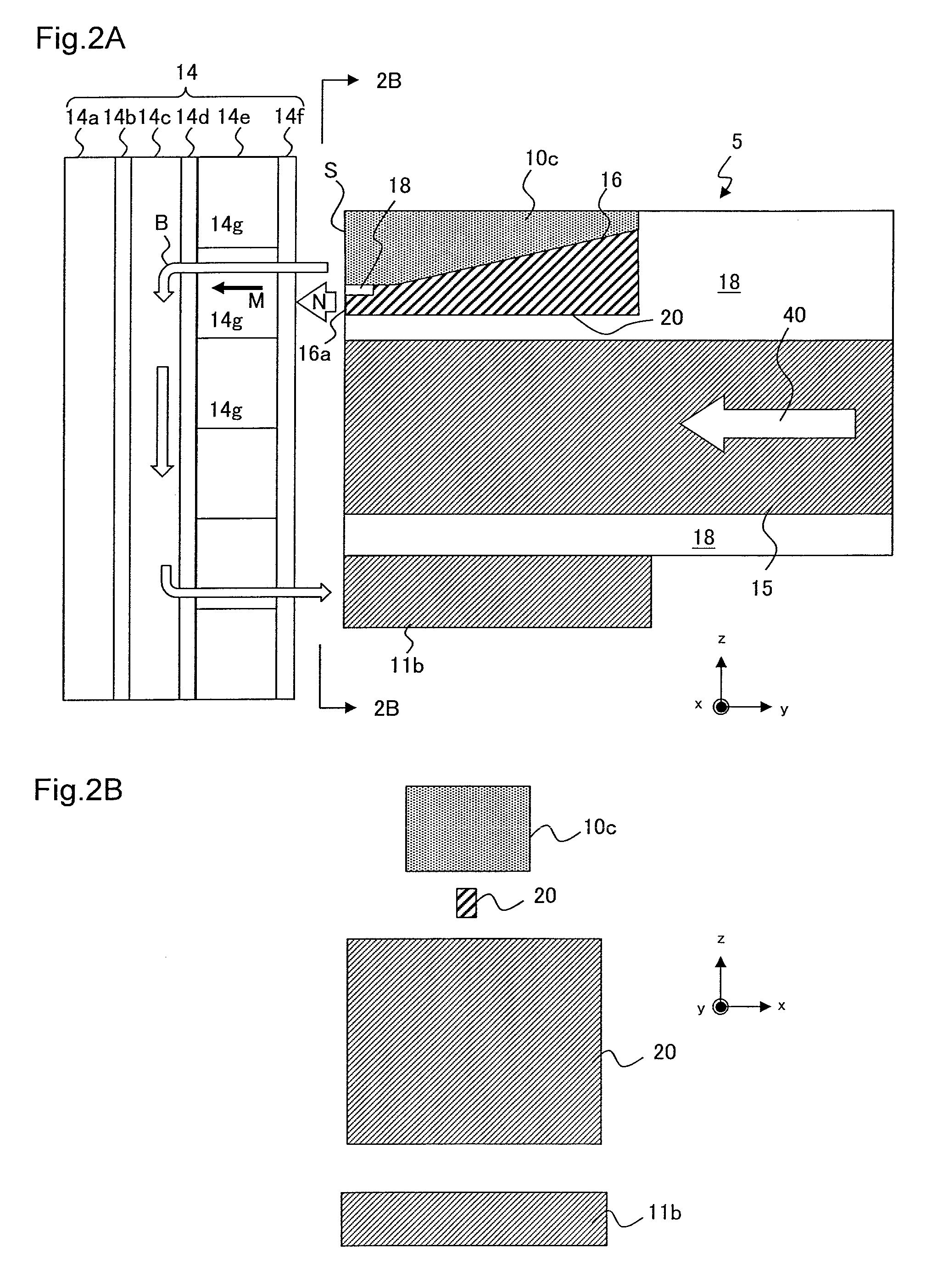
[0026]A thermally assisted magnetic recording head of the present invention is explained with reference to the drawings. FIG. 1 is a conceptual cross sectional view of the thermally assisted magnetic recording head. FIG. 2A is a main portion cross sectional view of the thermally assisted magnetic recording head and a magnetic recording media. FIG. 2B is a main portion side view of an air bearing surface S of the thermally assisted magnetic recording head from the perspective of the 2B-2B line of FIG. 2A. In the present specification, the “x” direction means a truck width direction of magnetic recording medium 14, the “y” direction means a direction perpendicular to the air bearing surface S of a magnetic head slider 2, the “z” direction means a direction perpendicular to a major plane 3a of substrate 3 (the major plain 3a meaning a surface on which an MR (Magneto Resistive) element 4, a magnetic recording element 5 and the like are formed). The “z” direction accords with the film fo...


PUM

PropertyMeasurementUnit
wavelengthaaaaaaaaaa
detectable wavelengthaaaaaaaaaa

Abstract

A thermally assisted magnetic recording head includes core that propagates laser light as propagation light, a near-field light generator that faces a portion of the core and extends to an air bearing surface (ABS), the near-field light generator coupled to the propagation light propagating through the core so as to generate a surface plasmon, propagating the surface plasmon to an end part facing the ABS, and generating near-field light at the end part to irradiate the near-field light to a magnetic recording medium, a main magnetic pole layer provided in the vicinity of the near-field light generator where an end part is positioned on the ABS, a laser diode that generates laser light of wavelength 890 nm to 1,000 nm and enters the laser light into the core, and a photodiode provided on a silicon substrate measures an intensity of the laser light entering from the laser diode to the core.

Description

BACKGROUND OF THE INVENTION[0001]1. Field of the Invention[0002]The present invention relates to a thermally assisted magnetic recording head and particular configuration of laser diode unit.[0003]2. Description of the Related Art[0004]Recently in the magnetic recording apparatus which representative the magnetic disk apparatus, the improvement performance of the magnetic recording medium and the thin film magnetic head is required with high density recording. Regarding the thin film magnetic head, the composite-type thin film magnetic head that is stacked with reproducing head with the magnetic resistive effect element for reading and recording head with induction-type electromagnetic transducer element for writing, have been widely used.[0005]The magnetic recording medium is the discontinuous medium on which the magnetic nanoparticles aggregate. Each magnetic nanoparticle has the single magnetic domain structure. Each recording bit on the magnetic recording medium is configured by...

Claims


Application Information

Patent Timeline
Patent Type & Authority Patents(United States)
IPC IPC(8): G11B11/00G11B5/31B01J19/12G11B5/60G11B5/00
CPCG11B5/314G11B5/6088G11B2005/0021
Inventor HARA, SHINJICHOU, TSUTOMUSHIMAZAWA, KOJIKOMURA, EIJITAKAYAMA, SEIICHIITO, YASUHIRO
Owner TDK CORPARATION
Learn More