
Electric connector and detection terminal included therein

a detection terminal and connector technology, applied in the direction of incorrect coupling prevention, coupling device connection, electrical apparatus, etc., can solve the problems of lock arm, safety device cannot operate accurately, corrosion might be imperfectly wiped, etc., and achieve the effect of high reliability of electrical connection

Inactive Publication Date: 2016-03-29
DAIICHI SEIKO CO LTD
View PDF14 Cites 0 Cited by
  • Summary
  • Abstract
  • Description
  • Claims
  • Application Information

AI Technical Summary

Benefits of technology

This design enhances the reliability of electrical connections by ensuring the lock arm returns to its original position, maintaining secure coupling and preventing safety device failures, even under conditions that might hinder its return.

Problems solved by technology

In particular, if electric signals could not be transmitted through male and female connectors in an electric connector employed in a safety device, because of imperfect coupling between the male and female connectors, the safety device would be unable to operate accurately.
However, if a resistance against the slide movement of the terminals 9 and 9′ relative to the resilient pieces 3c and 3c′ were increased, the terminals 9 and 9′ would be engaged with the resilient pieces 3c and 3c′ when the lock arm 6 is inclining (see FIG. 25) before the lock arm 6 returns back to its original position (see FIG. 24), resulting in that the above-mentioned contamination or corrosion might be imperfectly wiped, and furthermore, the lock arm 6 might not be able to return back to its original position, resulting in that the first and second connector housings 1 and 2 are incompletely coupled to each other.
If so, since signal lines connected by the first and second connector housings 1 and 2 are cut, a safety unit cannot operate even in an emergency.

Method used


Image

  • Electric connector and detection terminal included therein
  • Electric connector and detection terminal included therein
  • Electric connector and detection terminal included therein

Examples


Embodiment Construction

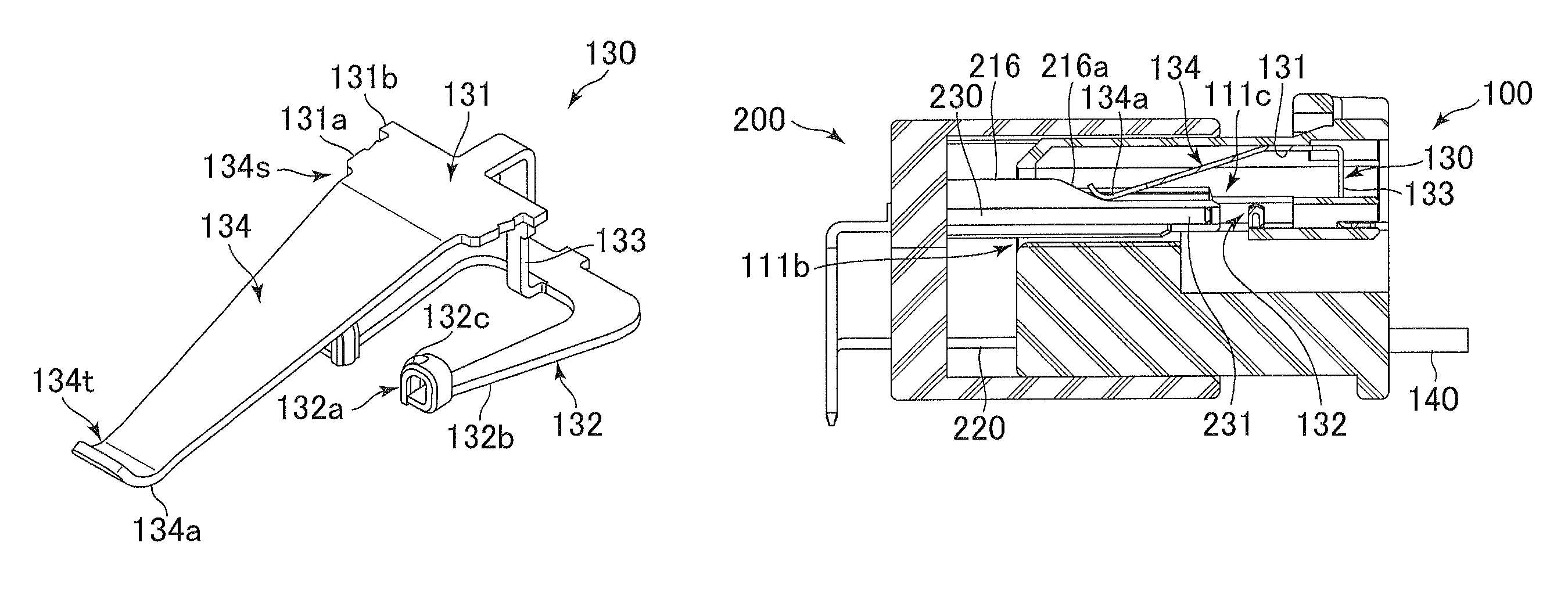
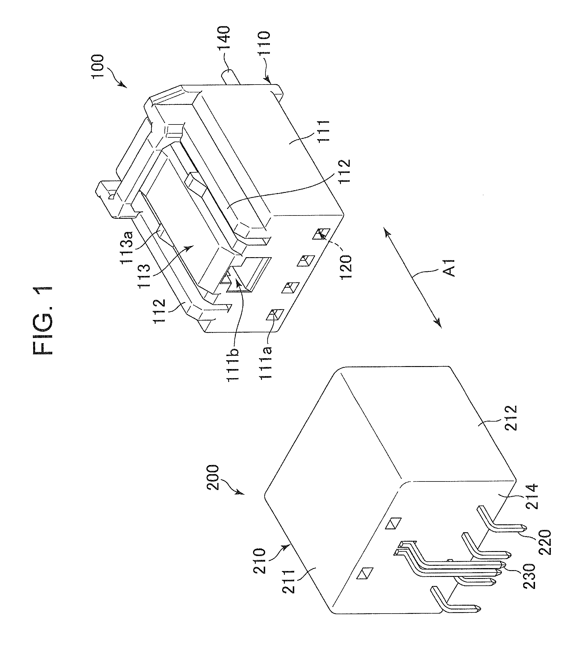
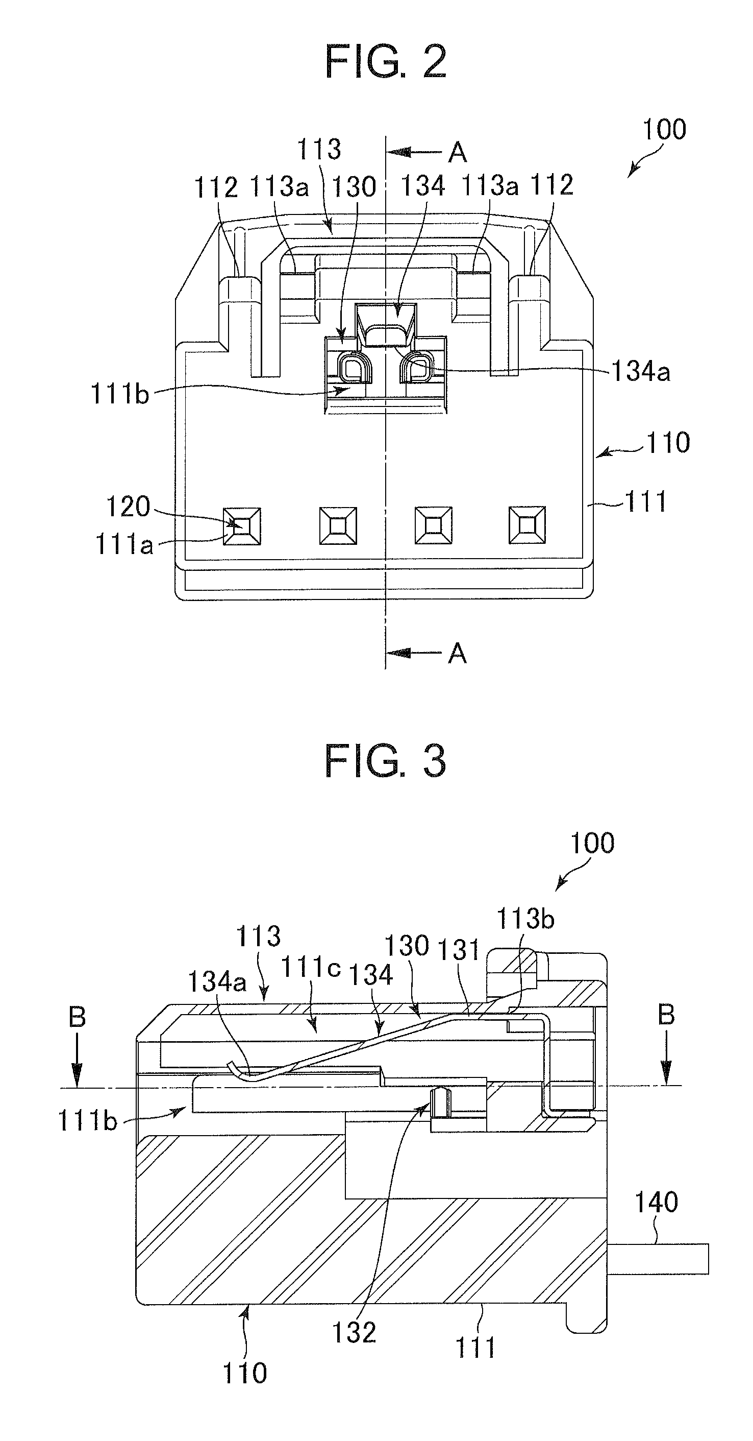
[0064]The electric connector in accordance with the preferred embodiment of the present invention is explained hereinbelow with reference to the drawings. In the specification, a “front” indicates a side of male and female electric connectors through which the male and female electric connectors are coupled to each other, and a “rear” indicates the opposite side to a “front”.

[0065]As illustrated in FIG. 1, the electric connector in accordance with the preferred embodiment of the present invention is embodied as a female electric connector 100. For instance, the female electric connector 100 in accordance with the current embodiment is employed together with a male electric connector 200 in a unit for operating an air bag equipped in an automobile. Specifically, the female and male electric connectors 100 and 200 are used to electrically connect wires used in the unit, to each other. Each of the female electric connector 100 and the male electric connector 200 is designed to include ...


PUM


Abstract

An electric connector includes a housing to be fit into a second electric connector, a lock arm resiliently deforming when the lock arm makes contact with an engagement part of the second electric connector, and thereafter, returning back to its original position, when the electric connector and the second electric connector are coupled to each other, a first detection terminal for detecting whether the electric connector and the second electric connector are electrically connected to each other, and a unit for assisting the lock arm to return back to the original position, the lock arm, the first detection terminal, and the unit being arranged in the housing, the detection terminal including a first portion to be fixed relative to the lock arm, and a second portion to make contact with a second detection terminal of the second electric connector.

Description

BACKGROUND OF THE INVENTION[0001]1. Field of the Invention[0002]The invention relates to an electric connector, and further to a detection terminal included in the electric connector for detecting whether the electric connector is electrically connected with a second electric connector.[0003]2. Description of the Related Art[0004]It is important for an electric connector defined with a male connector and a female connector to ensure that male and female connectors are surely coupled to each other to transmit electric signals therethrough. In particular, if electric signals could not be transmitted through male and female connectors in an electric connector employed in a safety device, because of imperfect coupling between the male and female connectors, the safety device would be unable to operate accurately. In order to avoid such a problem, an electric connector is generally designed to include a detection terminal for detecting whether male and female connectors are electrically ...

Claims


Application Information

Patent Timeline
Patent Type & Authority Patents(United States)
IPC IPC(8): H01R13/641H01R13/703H01R13/627
CPCH01R13/641H01R13/7032H01R13/6272
Inventor HASHIMOTO, YOSHIMITSUMORITA, TAKASHIJINNOUCHI, SHOGO
Owner DAIICHI SEIKO CO LTD
Learn More