System for providing power and data transmission between a door and a frame
a technology of power and data transmission and door frame, which is applied in the direction of instruments, individual entry/exit registers, inductances, etc., can solve the problems of fine wires being used and the risk of shock to a person passing through the door, so as to minimize the air gap and minimize the air gap
- Summary
- Abstract
- Description
- Claims
- Application Information
AI Technical Summary
Benefits of technology
Problems solved by technology
Method used
Image
Examples
first embodiment
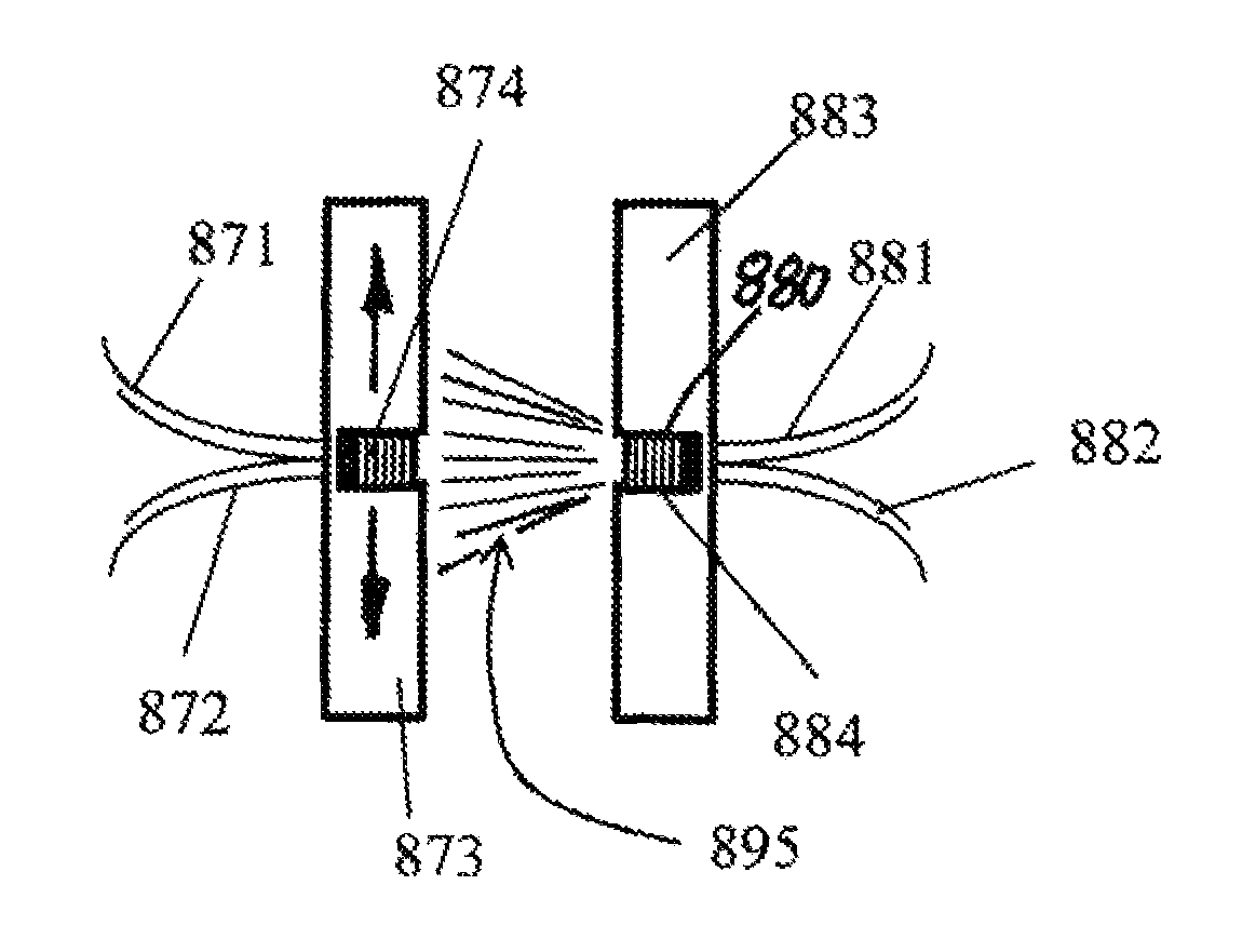
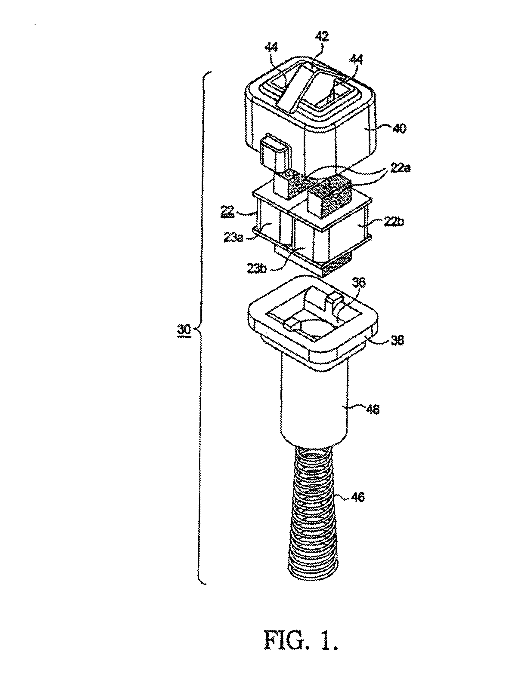
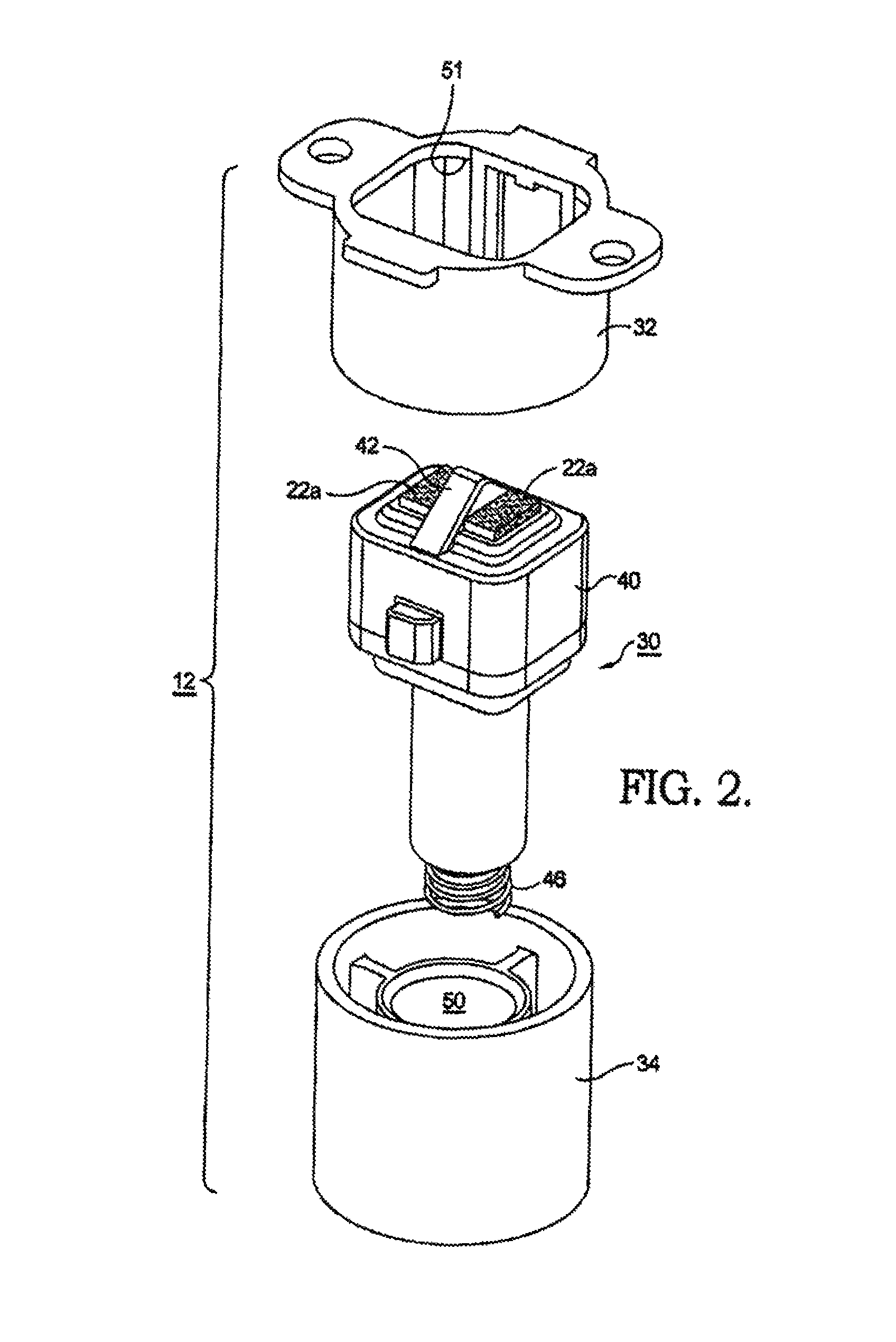
[0043]Referring now to FIGS. 1 through 9, the present invention generally relates to a system 10 which contains a method for providing power to an entry system device 12 located on a door 14 hinged in a frame 16 and for providing data transfer between an entry system device 12 and its mating device 18 on the frame side of the door through a split core electromagnetic transformer 20 comprising first and second transformer core portions 24, 22 disposed respectively in frame device 18 and door device 12. The first embodiment provides circuitry to enable such communication to occur at a Baud rate of essentially twice the frequency of the voltage being transferred between the door and frame side.
[0044]The present invention is applicable to doors, windows, or other objects that are moveable relative to a frame or other fixed object, wherein there is a need to communicate without direct electrical connection between a device located on the first object and a device located on the second ob...
second embodiment
[0086]Turning next to the door side of the present invention, FIG. 15 provides an illustrative schematic diagram of a circuit 174 as implemented on the door side of this alternate embodiment. Similar to the frame side, circuit 174 comprises power winding set L5 and data windings L4, L6.
[0087]Power from the frame side is provided through primary winding L5a and induces a current in secondary winding L5b. Capacitor C6 is in parallel with secondary winding 5b to cause resonance. The secondary winding L5b is in electrical connection with bridge rectifier D3. Bridge rectifier D3 converts the received sine wave to a full wave rectified signal 176. A filter capacitor C5 is located in parallel across the output terminals of the rectifier D1. The full wave rectified and filtered signal 176 is applied to a voltage regulator U1.
[0088]The regulator U1 provides the necessary voltage Vout to charge a built-in battery BAT1 and provide power to the door side circuit 174. A voltage regulator such as...
PUM
| Property | Measurement | Unit |
|---|---|---|
| width | aaaaa | aaaaa |
| output voltage | aaaaa | aaaaa |
| output voltage | aaaaa | aaaaa |
Abstract
Description
Claims
Application Information
 - R&D
- Intellectual Property
- Life Sciences
- Materials
- Tech Scout
- Unparalleled Data Quality
- Higher Quality Content
- 60% Fewer Hallucinations
Browse by: Latest US Patents, China's latest patents, Technical Efficacy Thesaurus, Application Domain, Technology Topic, Popular Technical Reports.
© 2025 PatSnap. All rights reserved.Legal|Privacy policy|Modern Slavery Act Transparency Statement|Sitemap|About US| Contact US: help@patsnap.com


