
Amorphous alloy stereo wound-core

a wound-core and alloy technology, applied in the direction of transformer/inductance details, basic electric elements, electrical equipment, etc., can solve the problems of inability to ensure the balance of three-phase power supply, inflexible design and manufacture, and high cost, so as to reduce the magnetic resistance and excited current largely, the effect of no high energy consumption area

Active Publication Date: 2013-05-02
HAIHONG ELECTRIC CO LTD
View PDF1 Cites 1 Cited by
  • Summary
  • Abstract
  • Description
  • Claims
  • Application Information

AI Technical Summary

Benefits of technology

This patent describes an improved design for an amorphous alloy stereo wound-core that solves issues with existing technologies. The design has lower vibration and lower excited current, reducing noise and improving efficiency. Additionally, there are no seams in the core, minimizing loss and achieving higher magnetic conduction. The result is a more reliable and efficient design for amorphous alloy cores.

Problems solved by technology

However, the cross sections of both structures are in a rectangular shape, the design of the transformer is thus restricted by the width of the amorphous alloy materials used, making the design and the manufacture inflexible.
In addition, these types of core structure make the transformer with higher weight, higher cost, bigger volume and longer processing time.
Thus, the balance of three-phase power supply cannot be guaranteed.
In addition, the occurrence of seams in the upper and lower iron yokes causes a high energy consuming area around the seams, so that the potential of the amorphous alloy sheets on high magnetic conductibility cannot be fully realized.
Furthermore, the air gap formed in the seams increase the corresponding loss.
Last but not least, the core and winding with a rectangular structure can reduce the ability of the products to withstand short-circuit.

Method used


Image

  • Amorphous alloy stereo wound-core
  • Amorphous alloy stereo wound-core
  • Amorphous alloy stereo wound-core

Examples


Embodiment Construction

[0010]Detailed descriptions for the embodiments of the invention will be made with reference to the drawings.

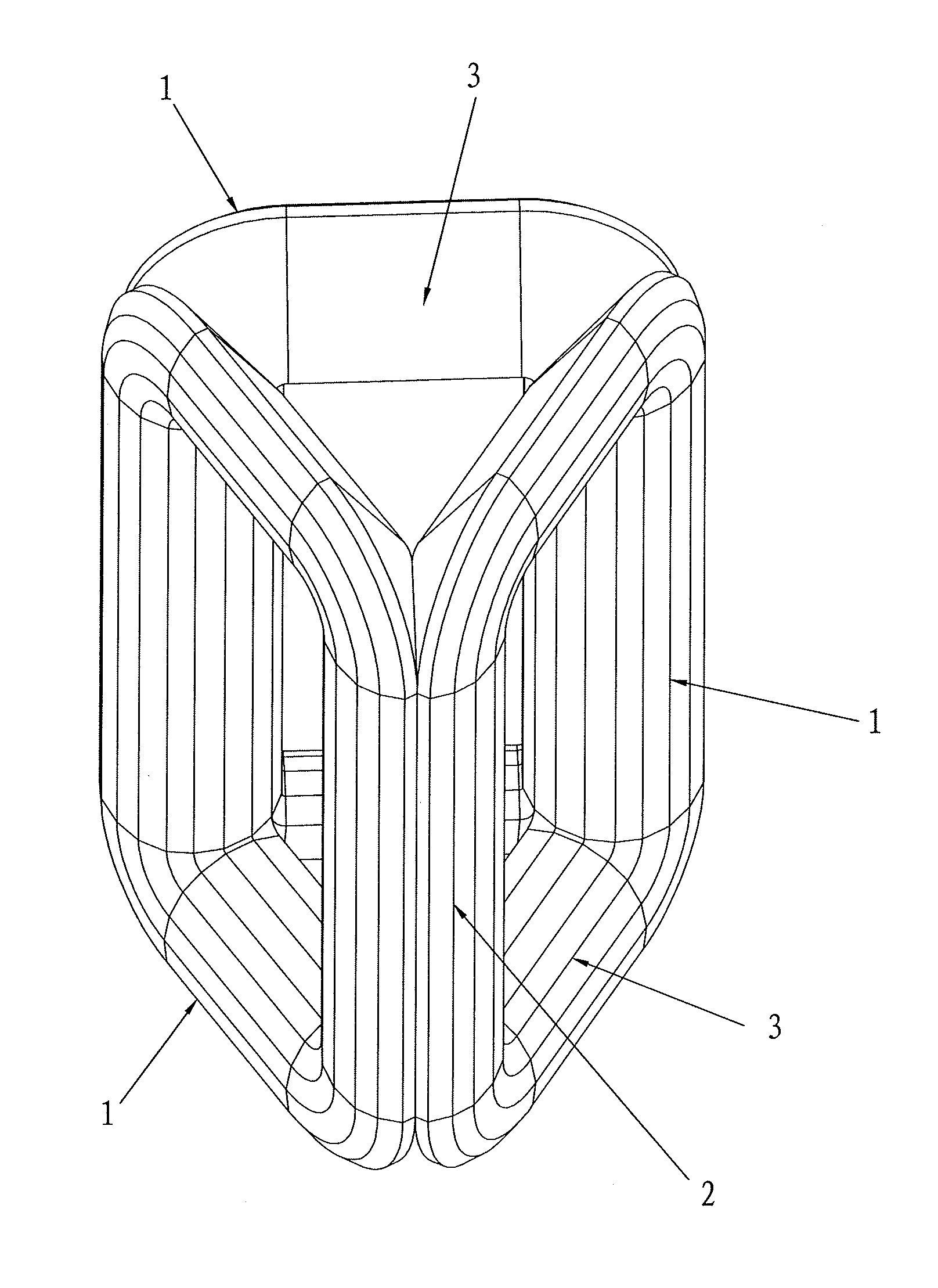
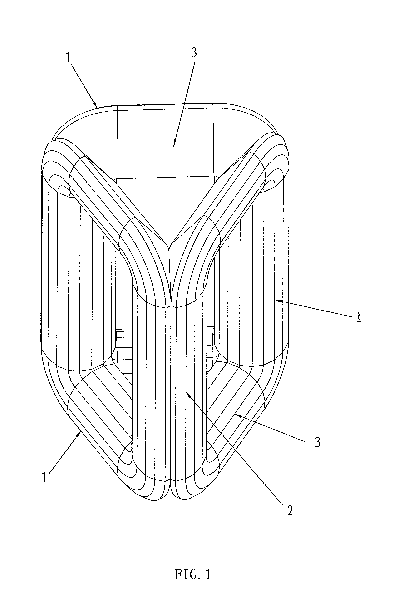
[0011]As shown in FIG. 1, the amorphous alloy stereo wound-core provided comprising three amorphous alloy made single frames 1 which are identical in structure and in a square shape. Each frame 1 is made of several trapezium strips wound in sequence consecutively. The cross section of the sides of the single frames 1 is in a semicircular or semi-polygonal shape.

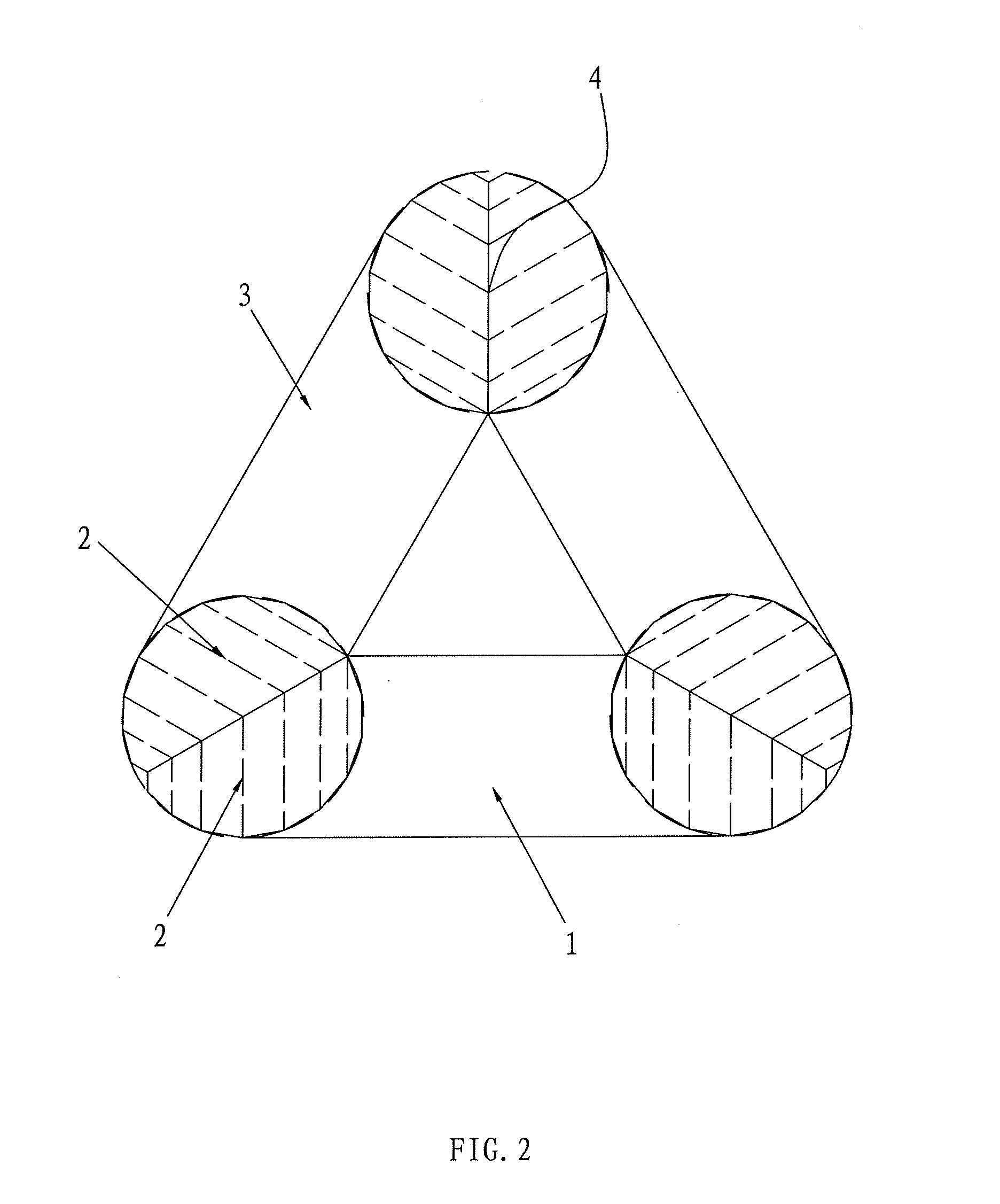
[0012]The single frames 1 are circularly and evenly distributed. The vertical sides of every two adjacent frames 1 fit together fixedly to form a core pillar 4. The horizontal sides of the frames 1 form iron yokes 3. As FIG. 2 shows, the cross section of each core pillar 4 is in a circular or polygonal shape.

[0013]Each single frame 1 is made of trapezium amorphous alloy strips wound from inside to outside consecutively.

[0014]Each single frame 1 is made of several trapezium amorphous alloy strips wound from inside to ou...


PUM

PropertyMeasurementUnit
shapeaaaaaaaaaa
thicknessesaaaaaaaaaa
Energy savingaaaaaaaaaa

Abstract

The invention provides an amorphous alloy stereo wound-core, comprising three structurally identical amorphous alloy made square frames; the cross section of the sides of the frames is in an approximately semi-circular or semi-polygonal shape; the frames have semi-circular cross sections and uniform thicknesses; the vertical sides of every two adjacent frames fit together fixedly to form a core pillar, the horizontal sides of the frames form iron yokes; the cross section of each core pillar has a circular or regular-polygonal shape. With this structure, the magnetic conduction direction of the amorphous alloy is completely consistent with the magnetic circuit direction of the core, and its working vibration is small. This core structure guarantees balanced three-phase power supply and largely reduces the magnetic resistance and excited current. There is no seam in the amorphous alloy stereo wound-core, so there is no area with high energy consumption. In this way, the advantages of the amorphous alloy on high magnetic conduction can be fully realized; the loss caused by an air gap in a seam is minimized. On the basis of the very low no-load loss of the conventional amorphous alloy, the present invention can further reduce the loss by 20% or more.

Description

TECHNICAL FIELD[0001]This invention is in the field of power equipment, and particularly relates to an amorphous alloy stereo wound-core.BACKGROUND[0002]Energy saving is a state policy necessary for a country to establish an energy-saving society. Because of the prominent advantages of energy saving and environmental protection, the amorphous alloy transformers are widely accepted by users, and become a new ideal type of distribution transformers. Currently for the existing amorphous alloy transformers in the market, the three-phase five-leg and three-phase three-leg core structures are commonly adopted. Comparing these two conventional amorphous alloy iron core structures, the three-phase three-leg iron core structure could be deemed as an updated version of the three-phase five-leg core structure, with relatively smaller volume, less weight, and less production time. However, the cross sections of both structures are in a rectangular shape, the design of the transformer is thus re...

Claims


Application Information

Patent Timeline
Patent Type & Authority Applications(United States)
IPC IPC(8): H01F3/04
CPCH01F3/04H01F41/0226H01F27/26H01F41/02H01F27/25
Inventor XU, KAIXUANGUO, XIANQING
Owner HAIHONG ELECTRIC CO LTD
Learn More