
Inspection apparatus, lithographic apparatus, and device manufacturing method

a technology of lithographic apparatus and inspection apparatus, applied in the field of inspection apparatus, can solve the problems of reducing system productivity, reducing the accuracy of ov and cd measurements, and reducing the working distance, so as to reduce the field curvature

Active Publication Date: 2016-03-15
ASML HLDG NV
View PDF21 Cites 2 Cited by
  • Summary
  • Abstract
  • Description
  • Claims
  • Application Information

AI Technical Summary

Benefits of technology

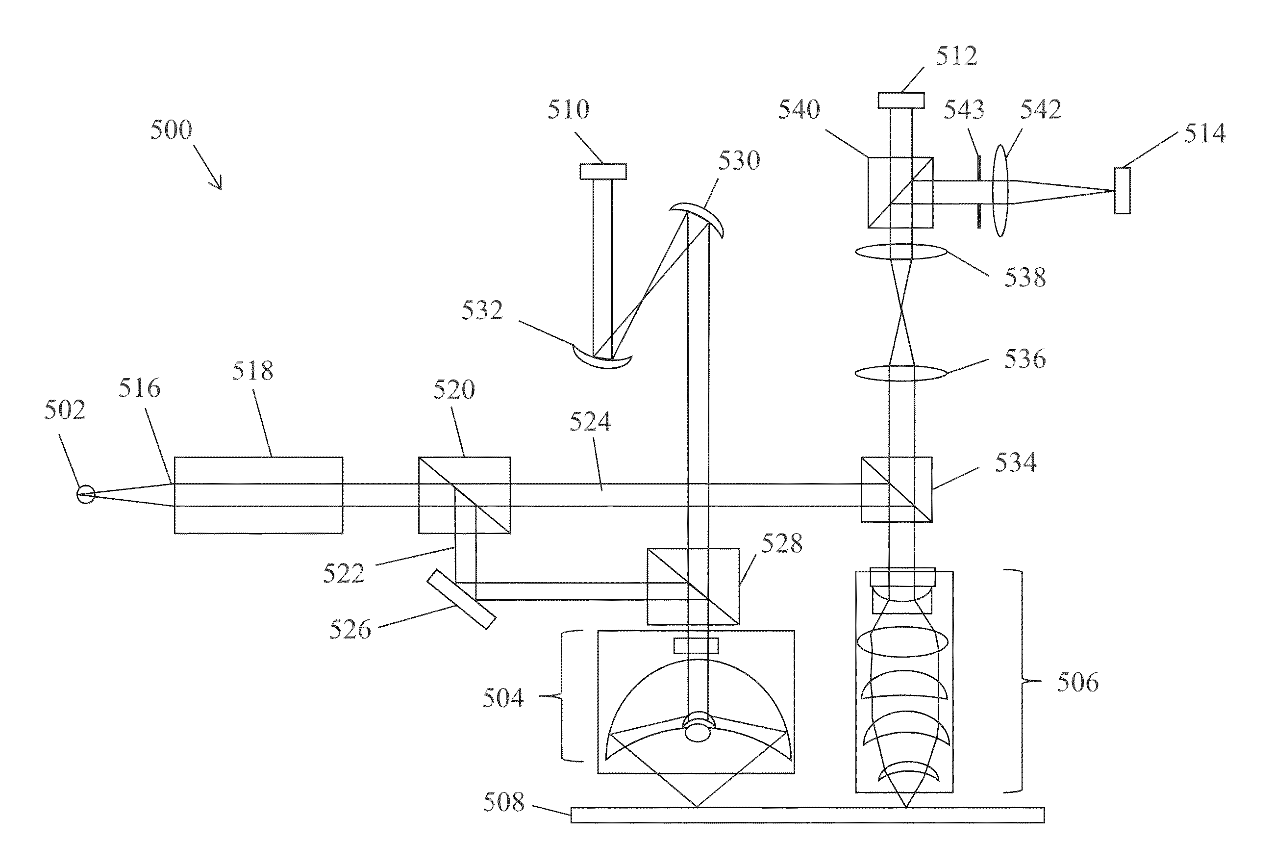
[0013]In another embodiment, an objective system, for example, an objective system that can be used with an inspection apparatus, includes a catadioptric objective and at least two mirrors configured to reduce field curvature induced by the catadioptric objective.

Problems solved by technology

Reduced optical performance can lead to reduced accuracy of the OV and CD measurements, as well as reduced system productivity.
One disadvantage of previous refractive objectives is that the working distance is relatively small.
Another disadvantage of previous refractive objectives is that the operational wavelength spectral range is limited to about 450-700 nm.
Further, previous refractive objectives only have plan apochromatic aberration correction.
One disadvantage of previous catadioptric objectives is that they induce field curvature—previous catadioptric objectives typically have a large Petzval sum that is far from zero.
Previous catadioptric objectives also suffer from obscuration that decreases image contrast.
Pupil aberrations in the previous catadioptric objectives are large because of large Petzval curvature and pupil size.

Method used


Image

  • Inspection apparatus, lithographic apparatus, and device manufacturing method
  • Inspection apparatus, lithographic apparatus, and device manufacturing method
  • Inspection apparatus, lithographic apparatus, and device manufacturing method

Examples


Embodiment Construction

[0035]This specification discloses one or more embodiments that incorporate the features of this invention. The disclosed embodiment(s) merely exemplify the present invention. The scope of the present invention is not limited to the disclosed embodiment(s). The present invention is defined by the claims appended hereto.

[0036]The embodiment(s) described, and references in the specification to “one embodiment”, “an embodiment”, “an example embodiment”, etc., indicate that the embodiment(s) described may include a particular feature, structure, or characteristic, but every embodiment may not necessarily include the particular feature, structure, or characteristic. Moreover, such phrases are not necessarily referring to the same embodiment. Further, when a particular feature, structure, or characteristic is described in connection with an embodiment, it is understood that it is within the knowledge of one skilled in the art to effect such feature, structure, or characteristic in connect...


PUM

PropertyMeasurementUnit
operational wavelength spectral rangeaaaaaaaaaa
wavelengthaaaaaaaaaa

Abstract

An inspection apparatus includes an illumination system that receives a first beam and produces second and third beams from the first beam and a catadioptric objective that directs the second beam to reflect from a wafer. A first sensor detects a first image created by the reflected second beam. A refractive objective directs the third beam to reflect from the wafer, and a second sensor detects a second image created by the reflected third beam. The first and second images can be used for CD measurements. The second beam can have a spectral range from about 200 nm to about 425 nm, and the third beam can have a spectral range from about 425 nm to about 850 nm. A third sensor may be provide that detects a third image created by the third beam reflected from the wafer. The third image can be used for OV measurements.

Description

CROSS-REFERENCE TO RELATED APPLICATIONS[0001]This application claims benefit under 35 U.S.C. §119(e) to U.S. Provisional Patent Application No. 61 / 542,440, filed Oct. 3, 2011; U.S. Provisional Patent Application No. 61 / 546,273, filed Oct. 12, 2011; and U.S. Provisional Patent Application No. 61 / 553,458, filed Oct. 31, 2011, which are all incorporated by reference herein in their entireties.BACKGROUND[0002]1. Field[0003]The present invention relates to an inspection apparatus usable, for example, in the manufacture of devices by lithographic techniques.[0004]2. Related Art[0005]A lithographic apparatus is a machine that applies a desired pattern onto a substrate, usually onto a target portion of the substrate. A lithographic apparatus can be used, for example, in the manufacture of integrated circuits (ICs). In that instance, a patterning device, which is alternatively referred to as a mask or a reticle, may be used to generate a circuit pattern to be formed on an individual layer of...

Claims


Application Information

Patent Timeline
Patent Type & Authority Patents(United States)
IPC IPC(8): G03F7/20
CPCG03F7/70625G03F7/70633G01N21/956G01B11/00G01N21/88G03F7/20
Inventor SMIRNOV, STANISLAV YRYZHIKOV, LEVCATEY, ERIC BRIANJOOBEUR, ADELHEALD, DAVIDSHMAREV, YEVGENIY KONSTANTINOVICHJACOBS, RICHARD
Owner ASML HLDG NV
Learn More