
Device and method for photo and video capture

a technology for video and photo capture, applied in the field of devices and methods for photo and video capture, can solve the problems of occupying extra space for multiple buttons on the form factor of camera devices, requiring more manufacturing, and disadvantages of techniques, so as to reduce hardware and its associated costs in design, reduce the effect of noticeably long time delay

Active Publication Date: 2016-03-01
SNAP INC
View PDF6 Cites 25 Cited by
  • Summary
  • Abstract
  • Description
  • Claims
  • Application Information

AI Technical Summary

Benefits of technology

The patent describes a technology for a camera device that uses a single user input element to detect different physical manipulation actions. This approach eliminates the need for multiple buttons and modes, reducing hardware costs and improving user experience. The technology detects actions based on the same type of physical manipulation, such as press and release actions, and can change states based on user needs. The camera device also uses the same image sensor for both photo and video capture, increasing portability and reducing costs.

Problems solved by technology

This technique can be disadvantageous in a number of ways.
For example, multiple buttons may require more hardware and its associated costs in design and manufacturing, as compared to a single button.
As another example, multiple buttons may occupy extra space on the form factor of the camera device.
As many modern camera devices are small in size for convenience and portability, there is limited space for user input elements, such as buttons.
This technique can be disadvantageous because an extra user operation is required to switch between these two modes.
This extra user operation and mode change introduces a noticeably long time delay before the user can press the capture button.
During that long time delay, the user may miss the opportunity to capture the desired photo or video.
The technique of this second example can be disadvantageous in a number of ways.
This extra physical manipulation of a different type introduces a noticeably long time delay before the user can press the single user input element.
During that long time delay, the user may miss the opportunity to capture the desired photo or video.
Additionally, accommodating multiple sliding positions may require more hardware and its associated costs in design and manufacturing, as compared to a single button occupying a single location.
Furthermore, multiple sliding positions may occupy extra space on the form factor of the camera device.

Method used


Image

  • Device and method for photo and video capture
  • Device and method for photo and video capture
  • Device and method for photo and video capture

Examples


embodiment 100

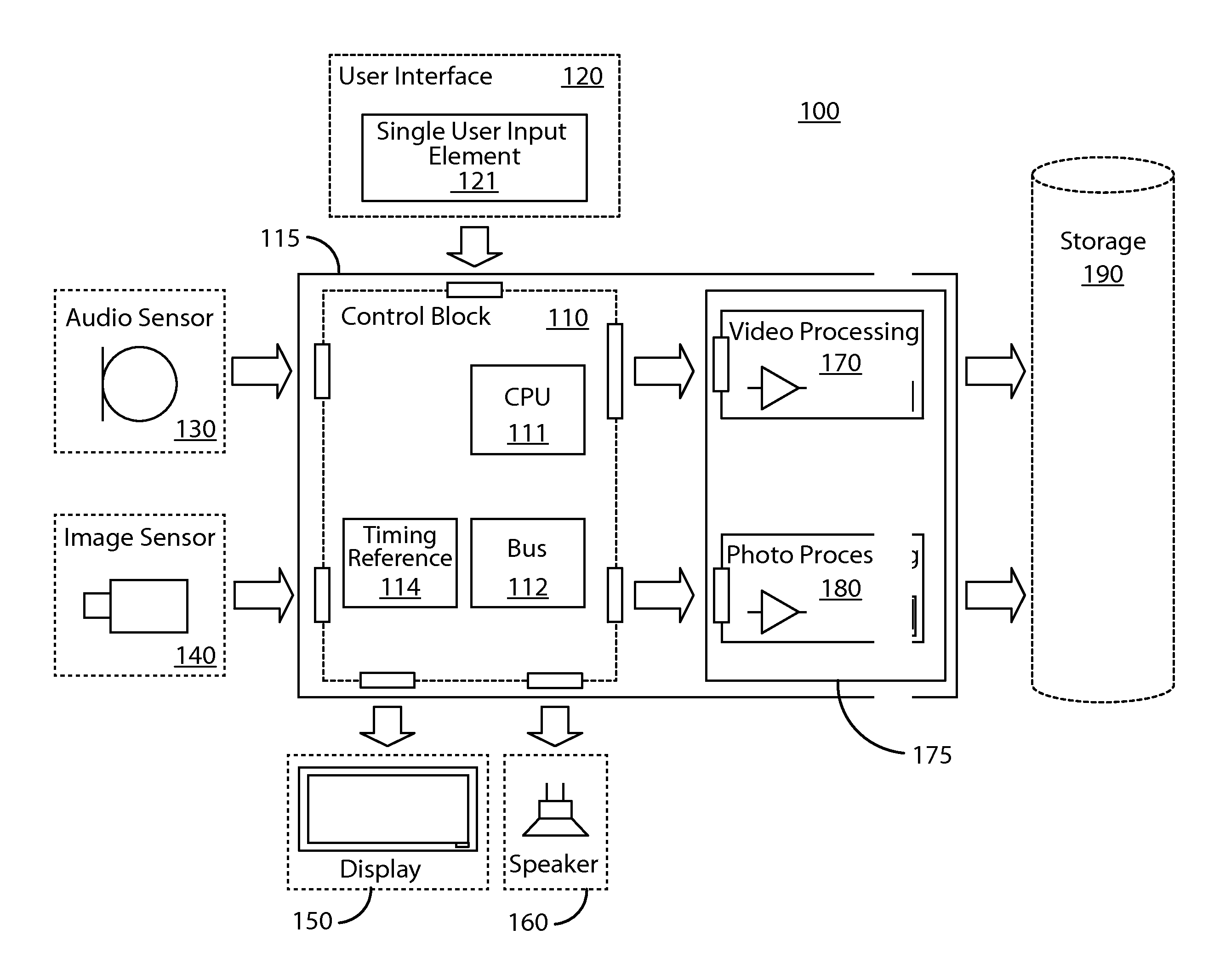
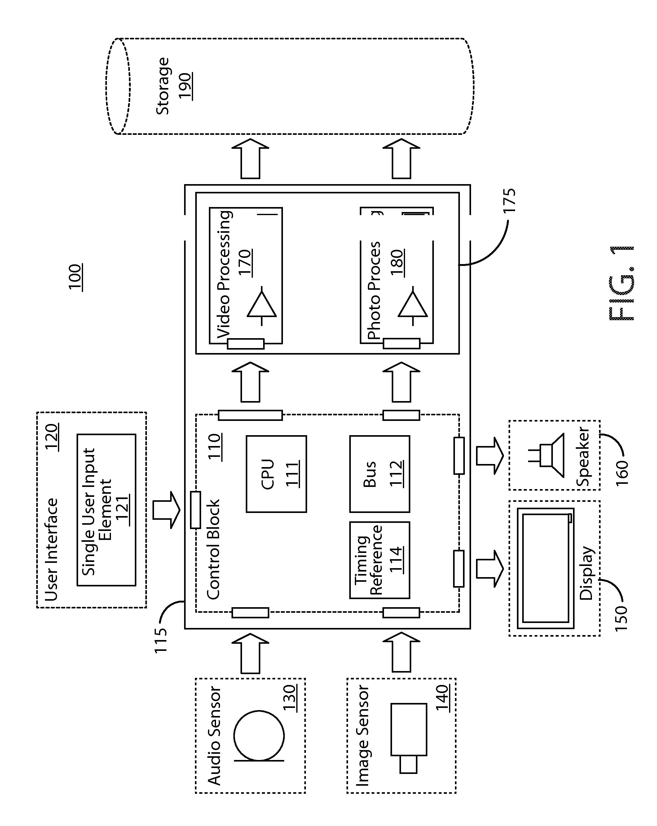
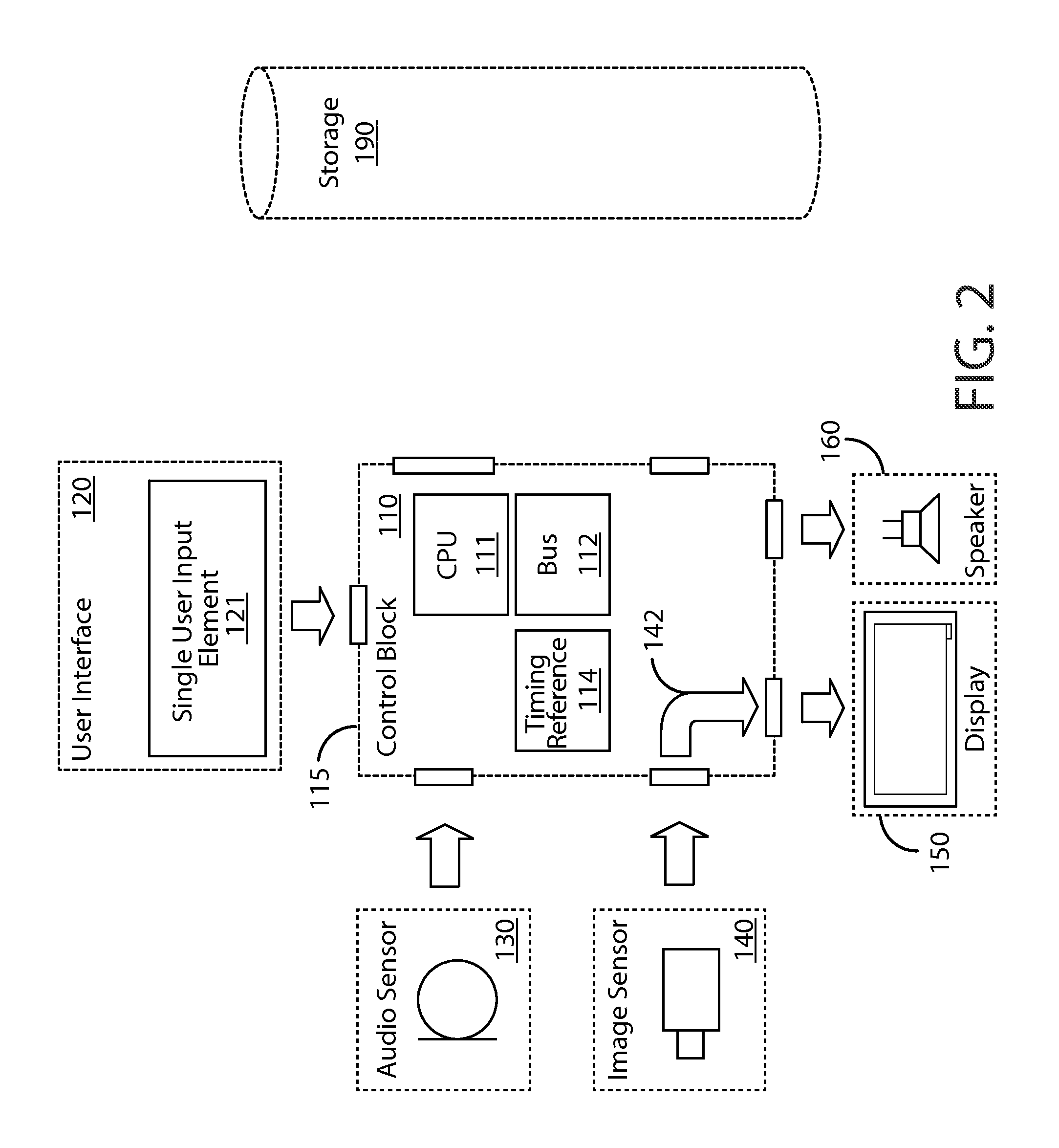
[0034]FIG. 1 is a block diagram of an overall system design in a preferred embodiment 100. Embodiment 100 may be implemented with any device configured to capture, process, store, or transmit (or any combination of the above steps) both photos and videos utilizing image sensors, such as image sensor 140. Such a device may also utilize audio sensors, such as audio sensor 130.

[0035]A user may issue commands to embodiment 100 to effectuate the capture of photo and / or video content. The user may be external to embodiment 100.

[0036]Control block 110 may represent the sequence of interactions between the user and embodiment 100 resulting in control commands and leading to the capture of photo and / or video content. Control block 110 may be implemented with central processing unit (CPU) 111, bus 112, and timing reference 114. CPU 111 may comprise one or more processors. Bus 112 may comprise one or more buses interconnecting the various components of embodiment 100. Timing reference 114 may ...

example interactions

[0085

[0086]The following discussion provides non-limiting examples of interactions with embodiment 100. From the perspective of a user, the user utilizes the single user input element 121 in two distinct patterns in order to acquire different representations of visual content.

[0087]As a first interaction pattern, the user may employ a relatively short interaction with element 121. For instance, the first interaction pattern may comprise a sequence of a brief touch and a release or a sequence of a brief press and a release. The time duration of the first interaction pattern is shorter than a pre-defined time interval, Interval X. The first interaction pattern triggers still image acquisition (e.g., static picture).

[0088]As a second interaction pattern, the user may employ a relatively longer interaction with element 121. For instance, the second interaction pattern may comprise a prolonged touch and a release or a sequence of a prolonged press and a release. The time duration of the ...


PUM


Abstract

A single user input element in an image capture device is used for both photo and video capture. Based on a first user interface activity, a timing reference is engaged at a first reference time. In a first case, photo capture is performed. In the first case, a second reference time is based on a second user interface activity, and the timing reference indicates a passage of time between the two reference times is shorter than a particular time interval. In a second case, video capture is performed. In the second case, the timing reference indicates a passage of time since the first reference time is equal to or longer than the particular time interval. Video capture is stopped based on a subsequent user interface activity. The user interface activities may comprise detecting actions based on the same type of physical manipulation of the single user input.

Description

REFERENCE TO RELATED APPLICATION[0001]This application is a continuation of U.S. patent application Ser. No. 13 / 596,041, filed Aug. 27, 2012, the entire contents of which is incorporated herein.FIELD OF THE INVENTION[0002]This relates to devices and methods for photo and video capture with a single user input element. The same single user input element in an image capture device is used in performing both photo capture and video capture.BACKGROUND OF THE INVENTION[0003]Image capture devices with the ability to capture both static content, such as still images, and dynamic content, such as moving images embodied as video or audiovisual content, have become widely available. Historically, still cameras for still images were distinct in design and functionality from video cameras for moving images. For instance, there has been a long history of some cameras designed for photography and other cameras designed for cinematography. Technological developments in image capture devices, howev...

Claims


Application Information

Patent Timeline
Patent Type & Authority Patents(United States)
IPC IPC(8): H04N5/232H04N5/77G03B17/00H04N5/222H04N1/21H04N9/79H04N101/00
CPCH04N5/23245H04N5/23206H04N5/23216H04N5/772H04N1/212H04N9/7921H04N2101/00H04N23/661H04N23/62H04N23/667H04N23/633H04N23/631
Inventor MARLIN, RICHARD, E.MATHIAS, MICHAEL, J.DIAKOV, KRISTIAN, D.
Owner SNAP INC
Learn More