Surgical instrument and system of surgical instruments

a surgical instrument and surgical instrument technology, applied in the field of surgical instruments, can solve the problems of difficult positioning of patients, inability to place cutting blocks on projections, and inability to manipulate patients, and achieve the effect of easy determination

Active Publication Date: 2016-03-01
DEPUY (IRELAND) LTD
View PDF36 Cites 1 Cited by
  • Summary
  • Abstract
  • Description
  • Claims
  • Application Information

AI Technical Summary

Benefits of technology

The present invention provides a surgical instrument with a mounting projection that can be easily installed on a mounting surface without requiring visibility of the mounting surface. The instrument has a recess that extends linearly, which allows it to cover more surface area of the mounting surface so the projection can be engaged more easily. The linear nature of the recess guides the projection towards the opening, providing tactile feedback to the surgeon as the mounting projection is moved towards the opening. This makes the surgical instrument easier to place on the mounting surface. Additionally, the mounting surface may have at least one further opening for receiving a mounting projection without a blind recess. This allows for slight repositioning of the instrument relative to the projections if required.

Problems solved by technology

Placing the cutting block on the projections is difficult.
However, it can be difficult to position the patient such that this view is available, or it can require unacceptable manipulation of the patient.
It can be difficult to identify the projections and openings accurately against the backdrop of the bright surgical lighting.
However, due to design constraints the chamfer can be very small.
This limits the usefulness of the chamfer.
If the cutting block is placed on more than one projection, for example a pair of projections, it can be difficult to place the cutting block if the projections have not been installed in precisely the correct position.

Method used


Image

  • Surgical instrument and system of surgical instruments
  • Surgical instrument and system of surgical instruments
  • Surgical instrument and system of surgical instruments

Examples


Embodiment Construction

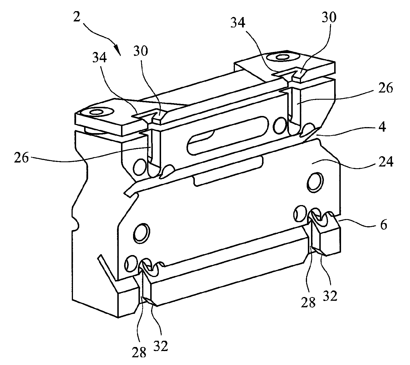
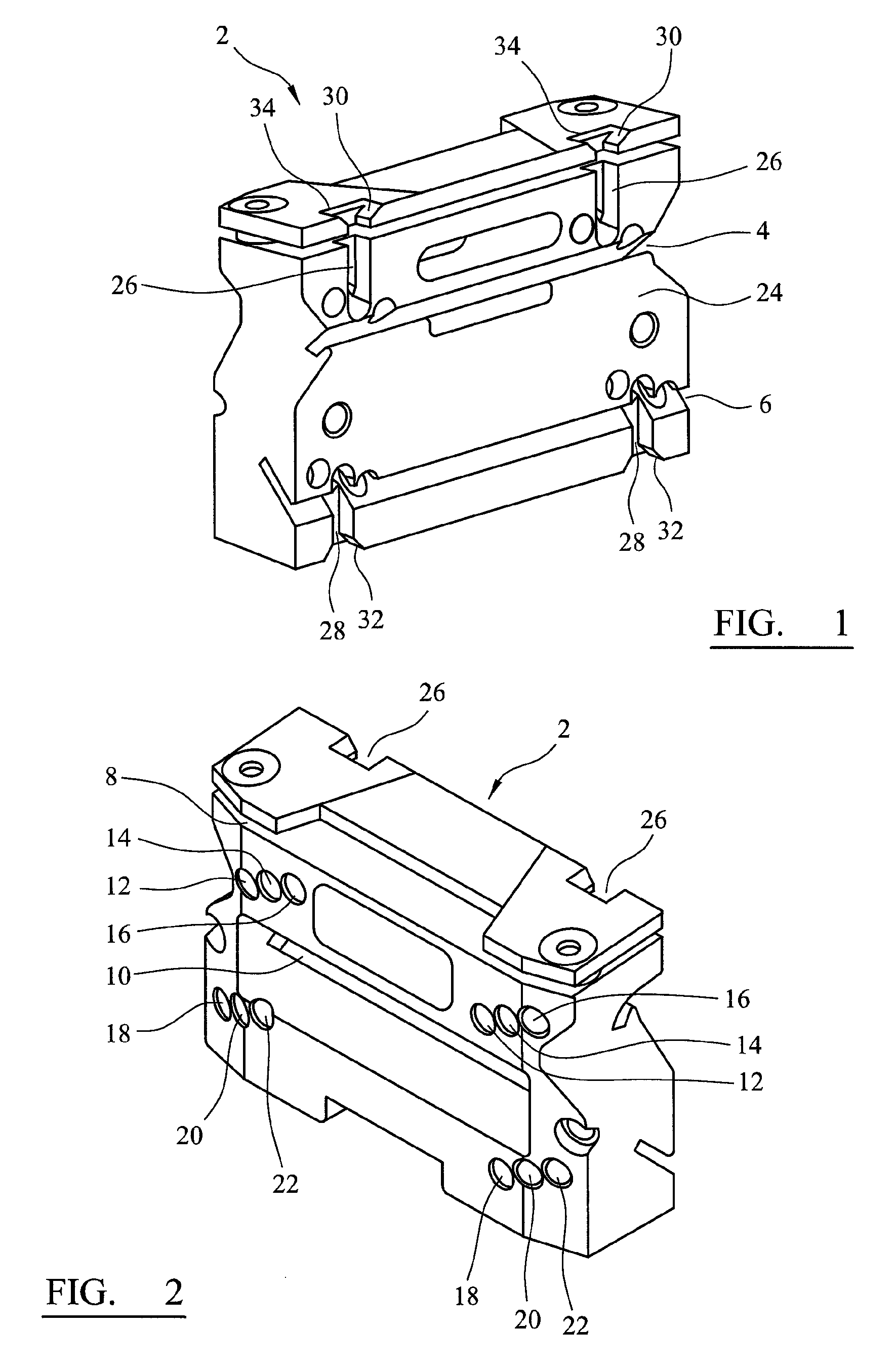
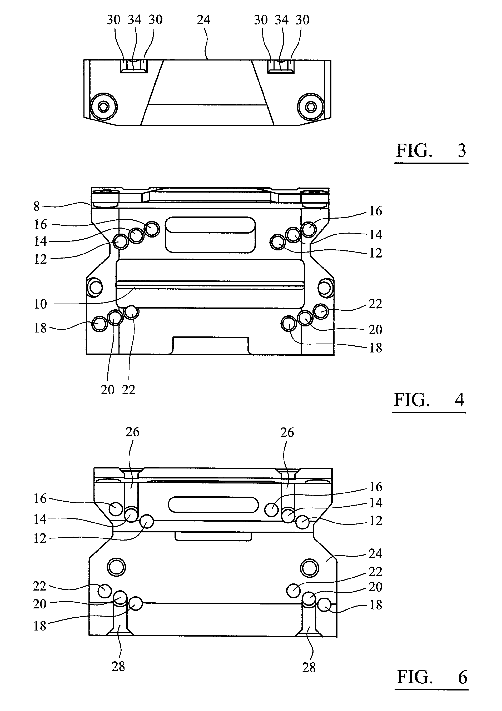
[0043]FIGS. 1-7 depict different views of a cutting block 2 according to the first embodiment of the invention. In this embodiment the cutting block is for use in knee surgery. It is a four-in-one cutting block, so called because a single cutting block can define four different cuts by guiding a cutting device through slots 4, 6, 8 and 10. In order to allow the cutting block 2 to be positioned on mounting projections or pins (not shown) the cutting block 2 defines a number of openings of through holes. Towards the top of the cutting block 2 three pairs of openings 12, 14, 16 define through holes. Each of the two openings in each pair, 12, 14, 16 are positioned the same distance apart but the pairs of openings 12, 14, 16 are offset slightly from each other. This enables the surgeon to adjust the position of the cutting block relative to the bone slightly in use, without needing to reposition the mounting projections.

[0044]Three more pairs of openings 18, 20, 22 are defined towards th...


PUM


Abstract

A surgical instrument, for example a cutting block for use in knee surgery, comprises a mounting surface defining at least one opening for receiving a mounting projection. The mounting surface further defines a blind recess which extends linearly from the at least one opening. The blind recess may extend to an edge of the mounting surface. A system including a surgical instrument and one or more mounting projections is also disclosed. The blind recess can be used as a track to guide a projection to an opening, increasing the area of the instrument that can be used to locate the projection in the correct position. The recess acts as a guide for the projection to enter the opening by providing tactile feedback to guide the projection towards the opening. If the recess also extends to the edge of the instrument, the recess may be visible more easily when the surgeon is installing the instrument providing visual as well as tactile feedback.

Description

CROSS REFERENCE TO RELATED APPLICATION[0001]This application is a National Stage 35 U.S.C. 371 of International Patent Application PCT / GB2010 / 051279, filed Aug. 3, 2010.BACKGROUND OF THE INVENTION[0002]The present invention relates to surgical instruments and in particular to surgical instruments that include openings for engaging projections to hold the surgical instrument in a particular position.[0003]Many surgical instruments require fixing in a known position relative to a patient. One example is a cutting block. Cutting blocks are typically affixed to a patient's bone in a position such that they can guide cutting and resection of the bone surface for receiving an implant.[0004]Existing cutting blocks are mounted to a patient's bone by engaging projections or pins in recesses. In some systems the projections extend from the cutting block and engage holes drilled in the bone. In other systems a fixed reference philosophy is used and the cutting block contains openings or holes ...

Claims


Application Information

Patent Timeline
Patent Type & Authority Patents(United States)
IPC IPC(8): A61B17/15A61B17/17
CPCA61B17/15A61B17/155A61B17/1764A61B17/154A61B17/17
Inventor YOUNG, DUNCAN
Owner DEPUY (IRELAND) LTD
Why Eureka
Try Eureka