Reduction of noise and vibrations of an electromechanical transducer by using a modified stator coil drive signal comprising harmonic components

a technology of stator coil and drive signal, which is applied in the direction of dynamo-electric converter control, dynamo-electric gear control, electric generator control, etc., can solve the problems of non-pm electromechanical transducers, which are equipped with commutators and brushes, are susceptible to significantly higher maintenance costs, cogging torque, and troublesome acoustic noise, so as to reduce unwanted vibrations

Active Publication Date: 2016-02-16
SIEMENS GAMESA RENEWABLE ENERGY AS
View PDF11 Cites 1 Cited by
  • Summary
  • Abstract
  • Description
  • Claims
  • Application Information

AI Technical Summary

Benefits of technology

[0011]There may be a need for reducing unwanted vibrations of an electromechanical transducer comprising a rotor being equipped with permanent magnets.

Problems solved by technology

In this respect, it is mentioned that non-PM electromechanical transducers, which are equipped with commutators and brushes, are typically susceptible to significantly higher maintenance costs.
One challenge of PM-electromechanical transducers is cogging torque.
In a PM-electric generator, cogging torque is an undesired effect that contributes to a so called “torque ripple” on the electric power output signal of the generator.
Another challenge of PM-transducers is the mechanical “radial force / pressure ripple”.
Both effects lead to unwanted vibrations of the PM-electric generator, which cause troublesome acoustic noise.
Avoiding or at least reducing acoustic noise and vibrations is a great challenge in the design and / or the operational control of PM-electric generators being used for wind turbines.
However, it is difficult to minimize both torque ripple and radial force / pressure ripple by using a single design for a PM-electromechanical transducer.
Therefore, it is very difficult to avoid vibrations within the whole frequency range of the PM electromechanical transducer.

Method used


Image

  • Reduction of noise and vibrations of an electromechanical transducer by using a modified stator coil drive signal comprising harmonic components
  • Reduction of noise and vibrations of an electromechanical transducer by using a modified stator coil drive signal comprising harmonic components
  • Reduction of noise and vibrations of an electromechanical transducer by using a modified stator coil drive signal comprising harmonic components

Examples


Embodiment Construction

[0071]The illustration in the drawing is schematically. It is noted that in different figures, similar or identical elements are provided with the same reference signs or with reference signs, which are different from the corresponding reference signs only within the first digit.

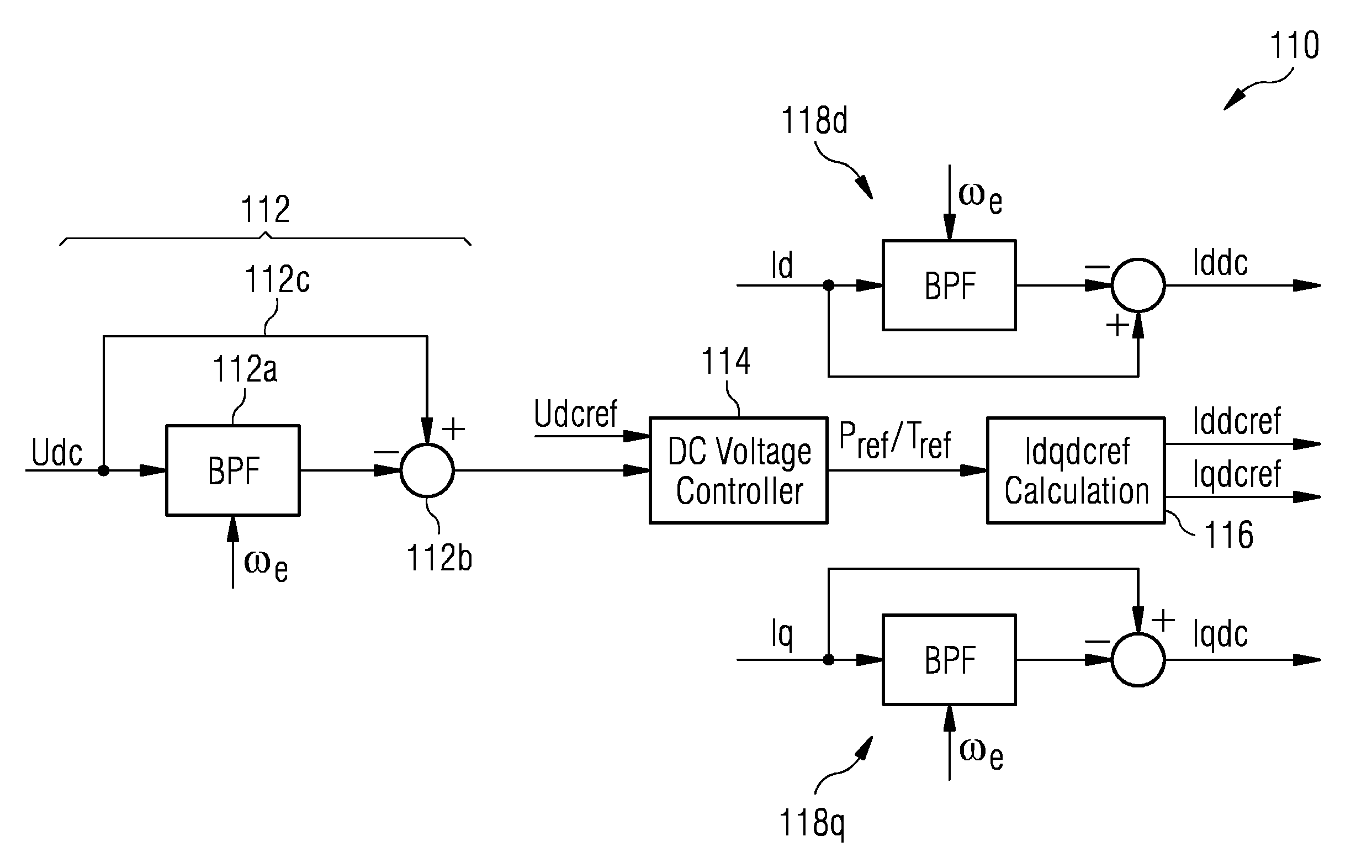
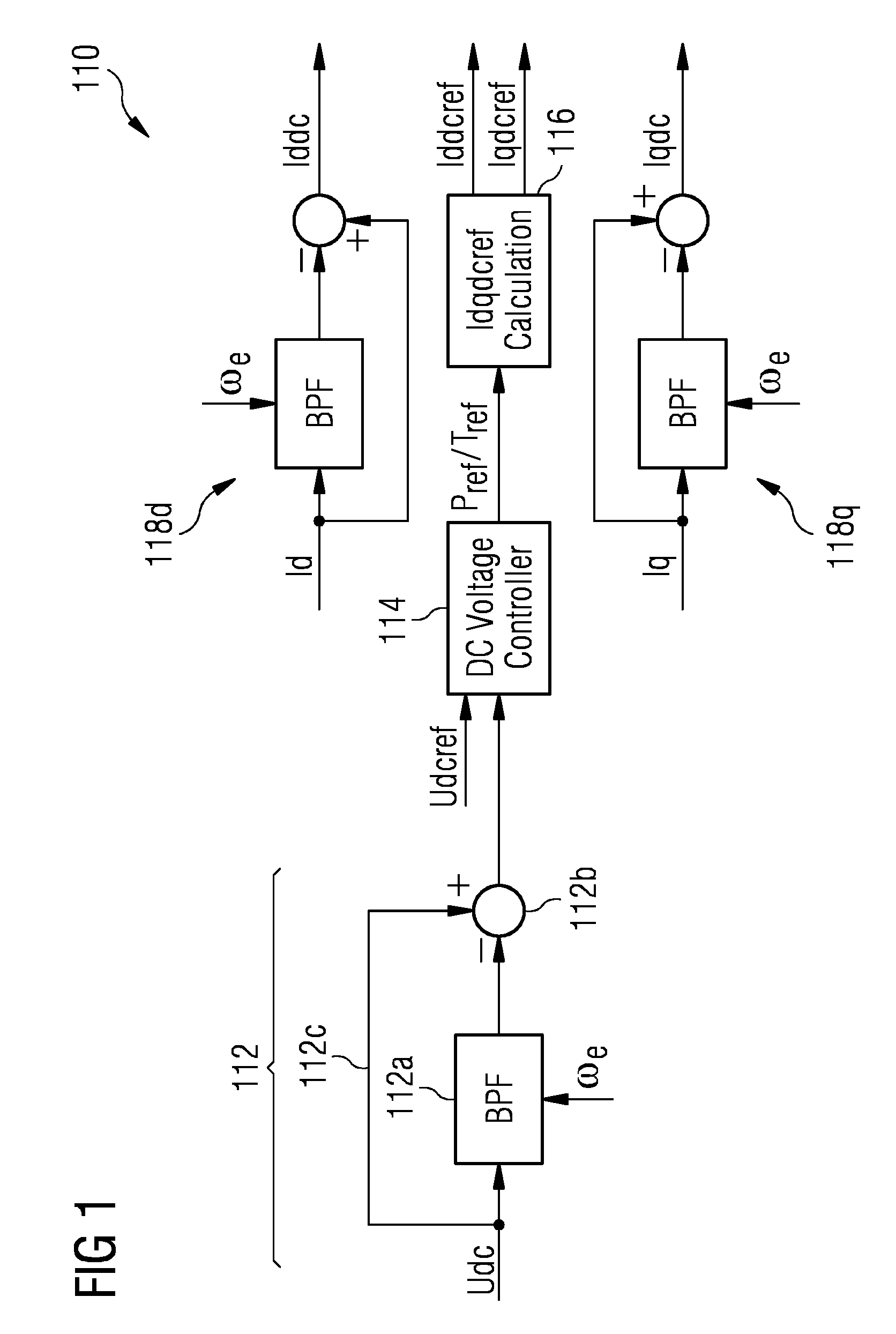
[0072]It is mentioned that in the following description all DC or AC signals or signal components refer to a d-q rotating reference frame. Of course, physically all electric signals being applied to the electric generator are AC signals.

[0073]FIG. 1 shows a fundamental controller 110 for controlling (a) a fundamental dc link voltage of a frequency converter and for controlling (b) the generation of a fundamental DC drive signal for electromagnetic coils of a stator of an electric generator, wherein the fundamental drive signal is associated exclusively with the fundamental operational behavior of the electric generator. The fundamental controller 110 comprises a band stop filter 112, which receives a signal ...


PUM


Abstract

A method for controlling the operation of an electromechanical transducer is provided. The method includes (a) determining during a first period of time a first strength of the harmonic operational behavior of the transducer, (b) determining during a second period of time a second strength of the harmonic operational behavior of the transducer, wherein the second period of time is different from the first period of time, (c) calculating a harmonic control signal in response to both the determined first strength of the harmonic operational behavior and the determined second strength of the harmonic operational behavior, (d) generating a modified drive signal based on the calculated harmonic control signal, and (f) supplying the generated modified drive signal to electromagnetic coils of a stator of the transducer. Further, a corresponding control system for controlling the operation of an electromechanical transducer is provided.

Description

CROSS REFERENCE TO RELATED APPLICATIONS[0001]This application claims priority of European Patent Office Application No. 11175583.1 EP filed Jul. 27, 2011. All of the applications are incorporated by reference herein in their entirety.FIELD OF INVENTION[0002]A method for controlling the operation of an electromechanical transducer, which in particular is an electric generator for a wind turbine, with a stator and a rotor is provided. Further, a control system and a computer program for controlling the operation of an electromechanical transducer are provided.ART BACKGROUND[0003]Electromechanical transducers are machines, which convert electrical energy into mechanical energy or vice versa. An electric motor is a widely used electromechanical transducer that converts electrical energy into mechanical energy using magnetic field linkage. An electric generator is an electromechanical transducer that converts mechanical energy into electrical energy also using a magnetic field linkage.[0...

Claims


Application Information

Patent Timeline
Patent Type & Authority Patents(United States)
IPC IPC(8): H02P9/02H02P29/00H02P101/15H02P21/00
CPCH02P9/02H02P29/0038H02P21/00H02P2101/15Y02E10/725H02P29/50Y02E10/72
Inventor DENG, HENG
Owner SIEMENS GAMESA RENEWABLE ENERGY AS
Why Eureka
Try Eureka