Valley-fill power factor correction circuit with active conduction angle control

a technology of conduction angle control and power factor correction, applied in the field of electrical circuits, can solve problems such as increasing the footprint of circuits, and achieve the effects of reducing the footprint, increasing the energy storage density, and improving the operational longevity and durability of circuits

Inactive Publication Date: 2016-02-16
TOUZELBAEV MAXAT
View PDF10 Cites 8 Cited by
  • Summary
  • Abstract
  • Description
  • Claims
  • Application Information

AI Technical Summary

Benefits of technology

[0007]A valley-fill circuit has power factor correction circuit with active conduction angle control. The valley-fill circuit uses a single storage capacitor instead of two. The capacitor is charged to the maximum voltage of the AC cycle, which increases energy storage density so that it is possible to use of low-capacitance high-voltage capacitors. This makes it feasible to use multilayer ceramic capacitors (MLCC), polyethylene, polypropylene, or other capacitors with similar low-capacitance high-voltage, low equivalent series resistance (ESR), or combinations of these, instead of electrolytic capacitors. This improves the operational longevity and durability of the circuitry and reduces its footprint. In many applications, electrolytic capacitors are chosen with higher than needed capacitance, in order to meet the requirements on the acceptable ESR, thus additionally increasing the circuit footprint.
[0008]In a specific implementation, a circuit includes: (1) a storage capacitor, implemented using a ceramic, polyethylene, polypropylene, electrolytic, or any other suitable type of capacitor, with one of terminals (negative if capacitor is polarized) connected to ground and another terminal connected to; (2) a parallel pair comprised of a first diode and a charge-current limiting resistor, connected in parallel to each other and in series to the storage capacitor, with diode, connected to conduct with capacitor discharge, to reduce resistive losses in charge limiting resistor, (3) a high-side switch implemented as a PMOS transistor, having an internal body diode and gate, drain, source electrodes, whose source is connected to current-limiting diode-resistor pair and whose drain is connected to an input to converter circuit; (4) a second diode, with cathode connected to an input to a converter circuit and an anode connected to an output from bridge rectifier, which is reverse-biased while storage capacitor discharges.
[0009]In general, a storage capacitor, charge-current limiting diode-resistor parallel pair, and a switch are connected in series in an arbitrary manner, provided that a switch element is effectively controlled during charge-discharge cycles. In this implementation, connection of source and drain electrodes of a typical PMOS transistor, implemented as high-side switch, reduces component count by making use of the built-in transistor body diode, whose anode is connected to a drain terminal of the transistor, which conducts with storage capacitor charging.

Problems solved by technology

In many applications, electrolytic capacitors are chosen with higher than needed capacitance, in order to meet the requirements on the acceptable ESR, thus additionally increasing the circuit footprint.

Method used


Image

  • Valley-fill power factor correction circuit with active conduction angle control
  • Valley-fill power factor correction circuit with active conduction angle control
  • Valley-fill power factor correction circuit with active conduction angle control

Examples


Embodiment Construction

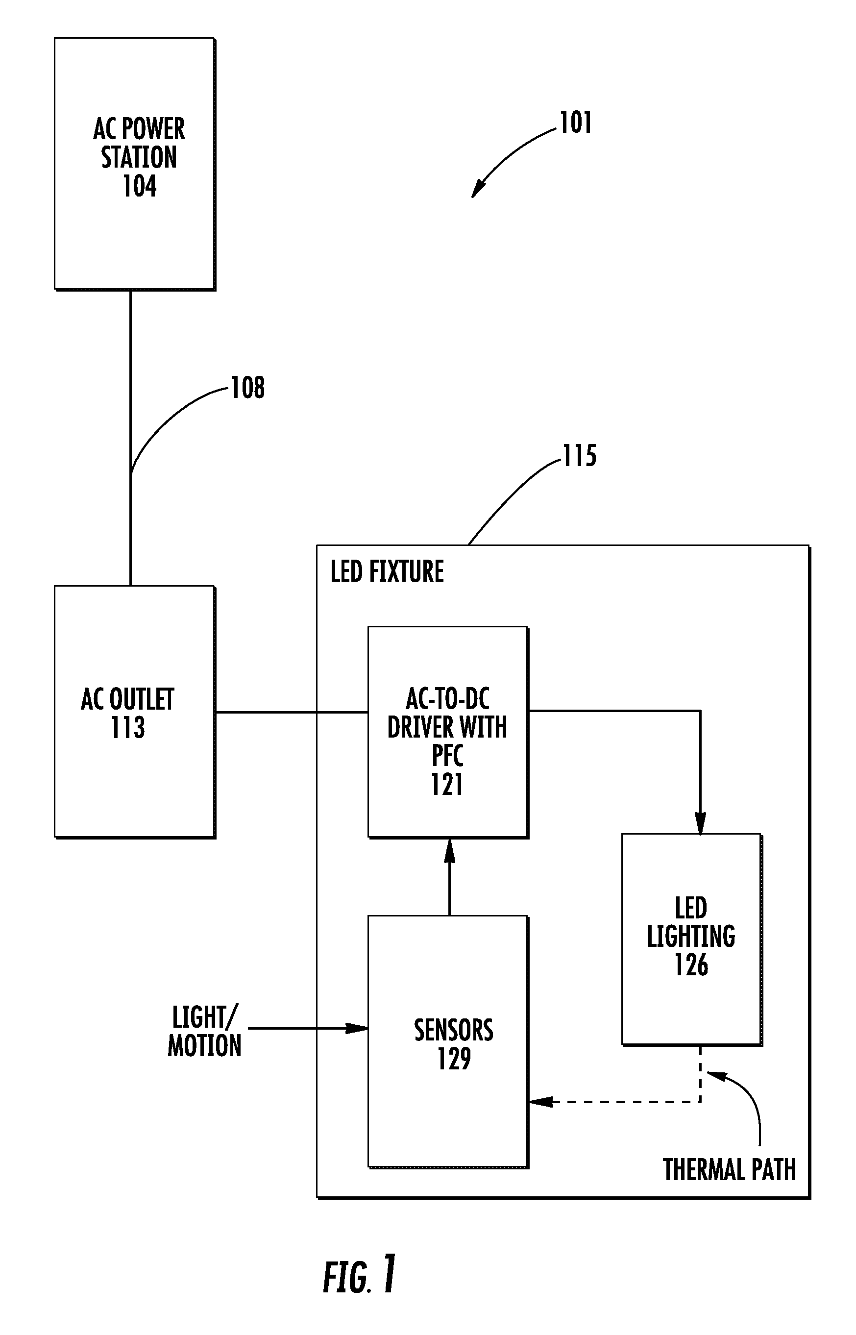
[0022]FIG. 1 shows an AC power distribution system 101 and a load connected to the system. Power is generated by an AC power station 104 and is distributed by transmission lines 108 to an outlet 113 (or other connection point) where an electrical load 115 is connected.

[0023]As an example, the load can be a light emitting diode (LED) lighting, such as used for street lighting or lighting inside a home. LED lighting uses direct current (DC) rather than alternating current (AC) power, which is provided by the AC power distribution system. So, the AC power is converted into DC power user an AC-to-DC converter 121. Since LED lighting is a current device, its driver should have provisions for current control.

[0024]FIG. 1 shows a single load as an example. In a typical system, there are numerous loads (e.g., 2, 3, 4, 8, 100s, 1000s, 10,000, or more). Some examples of loads of a system include street lighting, signal lights, computers, televisions, and many others.

[0025]DC current is suppli...


PUM


Abstract

A valley-fill circuit with active conduction angle control allows use of a single storage capacitor instead of two. The capacitor is charged to the maximum voltage of the AC cycle, which makes possible use of low-capacitance high-voltage low ESR capacitors, increases energy storage density and decreases circuit footprint. This makes it feasible to use ceramic capacitors, such as a multilayer ceramic (MLCC), polyethylene, polypropylene, or any suitable capacitor type in addition to electrolytic capacitors. This improves the operational longevity and reduces the footprint of the circuitry.

Description

CROSS-REFERENCE TO RELATED APPLICATIONS[0001]This patent application claims priority to U.S. patent application 61 / 924,180, filed Jan. 6, 2014, which is incorporated by reference along with all other references cited in this application.BACKGROUND OF THE INVENTION[0002]This invention relates to electrical circuits and more specifically to a power supply designed for the use with durable, long lifespan components while having acceptable power factor.[0003]For alternating current (AC) distribution of electrical power, power factor is the ratio of the real power flowing to a load, to the apparent power in the circuit, and is a dimensionless number between −1 and 1. Real power is the capacity of the circuit for performing work in a particular time. Apparent power is the product of the current and voltage of the circuit.[0004]Due to energy stored in the load and returned to the source, or due to a nonlinear load that distorts the wave shape of the current drawn from the source, the appar...

Claims


Application Information

Patent Timeline
Patent Type & Authority Patents(United States)
IPC IPC(8): H05B41/16H05B33/08H02M3/156H05B44/00
CPCH02M3/156H05B33/0815H02M1/4208Y02B70/10H05B45/375
Inventor TOUZELBAEV, MAXAT
Owner TOUZELBAEV MAXAT
Why Eureka
Try Eureka