Integrated brake component mounting bracket

a technology for mounting brackets and brake components, which is applied in the direction of braking components, machine supports, brake systems, etc., can solve the problems of reducing the ability of leaf springs to withstand stress, slowing or stopping vehicles, and not providing a stable structural mounting surfa

Active Publication Date: 2016-02-16
HENDRICKSON USA L L C
View PDF14 Cites 4 Cited by
  • Summary
  • Abstract
  • Description
  • Claims
  • Application Information

AI Technical Summary

Benefits of technology

[0018]An objective of the present invention is to provide a brake component mounting bracket that enables a brake chamber and a cam shaft assembly to be rigidly mounted on or adjacent to the vehicle axle without welding a brake chamber bracket or a cam shaft assembly mounting bracket to the axle.
[0019]Another objective of the present invention is to provide a brake component mounting bracket that enables the use of a thinner-wall axle, thereby reducing the weight and cost associated with the axle / suspension system.

Problems solved by technology

Rotation of the S-cam forces brake linings or pads to make contact with the brake drum to create friction and thus slow or stop the vehicle.
Because it is not feasible to mount the brake chamber bracket and / or the cam shaft assembly mounting bracket directly on or to a leaf spring, these brackets have been mounted on the axle in the prior art.
More particularly, the leaf spring must flex to dampen forces and thus does not provide a stable structural mounting surface.
In addition, because a leaf spring is formed with a metallurgical structure that enables it to flex while withstanding significant stress, attempting to mount such brackets directly on or to the leaf spring may significantly decrease the ability of the leaf spring to withstand stress.
However, this configuration has certain disadvantages, including a susceptibility to stress.
As a result, when forces and resulting loads act upon the axle, a welded area along the axle central tube is generally more susceptible to possible damage from such forces and / or loads than a non-welded area.
In order to compensate for the increased susceptibility to stress that is caused by welds, the wall thickness of the axle typically is increased, which undesirably increases the amount of material used to manufacture the axle, and also increases the weight of the axle.
Thus, in the prior art, the use of a brake chamber bracket and a cam shaft assembly mounting bracket that are each welded to the axle central tube has required the use of a relatively-thick-walled axle, which undesirably increases the cost and weight of the axle.
However, such mounting structures cannot be employed in a spring axle / suspension system because air-ride axle / suspension systems are different in structure and operation from spring axle / suspension systems.
Due to the different structural requirements and operation of box-type beams of an air-ride axle / suspension system and leaf springs of a spring axle / suspension system, it is not feasible to attach the brake chamber bracket and the bearing bracket directly to a leaf spring.
In contrast, spring axle / suspension systems do not employ air springs, instead relying on the leaf springs to flex and thus dampen forces.
Because the leaf springs flex during vehicle operation, they do not provide a sufficient stable structural mounting surface to enable the mounting of components such as the brake chamber or brake chamber bracket and the cam shaft assembly mounting bracket.
In addition, because leaf springs are formed with a metallurgical structure that enables them to flex while withstanding significant stress, it is undesirable to attempt to mount such components or brackets on the leaf springs, as such mounting may significantly decrease the ability of the leaf springs to withstand stress.

Method used


Image

  • Integrated brake component mounting bracket
  • Integrated brake component mounting bracket
  • Integrated brake component mounting bracket

Examples


first embodiment

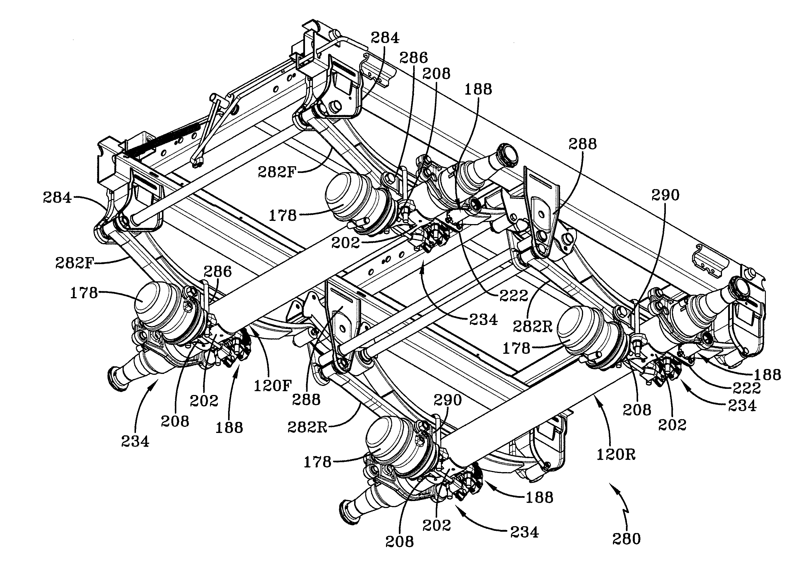
[0063]With particular reference now to FIG. 6, integrated brake component mounting bracket 200 includes a bottom axle seat 202, an air chamber mounting bracket 208, and a cam shaft assembly mounting bracket 222, which is also referred to as an S-cam bearing bracket. More particularly, bottom axle seat 202 is a curved plate that seats against a lower portion of each axle 120F, 120R and preferably is welded to each respective axle in the invention. Bottom axle seat includes a front portion 204 and a rear portion 206, and bosses 170 are integrally formed on the seat to receive U-bolts 164, as described above.

[0064]With additional reference to FIG. 8, air chamber mounting bracket 208 of integrated brake component mounting bracket 200 is rigidly attached to front portion 204 of bottom axle seat 202. More particularly, air chamber mounting bracket 208 includes a mounting plate 210 that is disposed generally parallel to each respective transversely-extending axle 120F, 120R. Mounting plate...

second embodiment

[0082]In regard to the mechanical attachment of top axle seat 236 and second embodiment integrated brake component mounting bracket 234 to each respective axle 120F, 120R, it is to be understood that other means of mechanical engagement of the top axle seat and the integrated brake component mounting bracket to each axle may be used, without affecting the concept or operation of the invention. For example, dimpling of top axle seat 236, integrated brake component mounting bracket 234, axle 120F, 120R, and / or an associated axle sleeve, as described in application Ser. No. 13 / 249,420, which is assigned to the same assignee as the present invention, Hendrickson USA, L.L.C., may be employed.

[0083]It is to be understood that integrated brake component mounting bracket of the present invention 200, 234, may be employed in conjunction with types of spring axle / suspension systems other than those shown and described herein, without affecting the overall concept or operation of the invention...

third embodiment

[0103 integrated brake component mounting bracket 300 enables the rigid attachment of air chamber mounting bracket 348 and cam shaft assembly mounting bracket 350 immediately adjacent each respective spring stack 312, 314 on an underslung axle / suspension system 302. This structural positioning provides stability of air chamber mounting bracket 348 and cam shaft assembly mounting bracket 350, which in turn enables brake chamber 178 and cam shaft assembly 188 to be rigidly mounted on or adjacent each axle 120F, 120R in a stable manner within the space constraints imposed by underslung axle / suspension system 302.

[0104]The present invention also includes a method of mounting a brake chamber and a cam shaft assembly to an integrated brake component mounting bracket, including steps in accordance with the description that is presented above and shown in FIGS. 5-17.

[0105]It is to be understood that the structure of the above-described integrated brake component mounting bracket of the pres...


PUM


Abstract

An integrated brake component mounting bracket for a mechanical spring axle / suspension system of a heavy-duty vehicle includes an axle seat that is disposed on and is rigidly connected to an axle of the vehicle. An air chamber mounting bracket is rigidly connected to the axle seat, and a cam shaft assembly mounting bracket is rigidly connected to the axle seat. A brake air chamber of a brake system is attached to the air chamber mounting bracket, and a cam shaft assembly of the brake system is mounted to the cam shaft assembly mounting bracket. The integrated brake component mounting bracket thus provides mounting of the brake air chamber and the cam shaft assembly on the axle seat, which reduces the number of components that are welded to the axle and enables the use of a thinner-wall axle, desirably reducing the weight and cost associated with the axle / suspension system.

Description

CROSS-REFERENCE TO RELATED APPLICATIONS[0001]This application claims the benefit of U.S. Provisional Patent Application Ser. No. 61 / 718,777, which was filed on Oct. 26, 2012.BACKGROUND OF THE INVENTION[0002]1. Technical Field[0003]The present invention relates to the art of brake component mounting for vehicles. More particularly, the invention relates to the art of mounting brake components on mechanical spring axle / suspension systems for heavy-duty vehicles, such as tractor-trailers or semi-trailers. Still more particularly, the invention relates to an integrated brake component mounting bracket for a mechanical spring axle / suspension system, which enables the brake chamber and the cam shaft assembly to be mounted on an axle seat, desirably reducing the number of components that are welded to the axle and enabling the use of a thinner-wall axle. The use of a thinner-wall axle desirably reduces the weight and cost associated with the axle / suspension system.[0004]2. Background Art[0...

Claims


Application Information

Patent Timeline
Patent Type & Authority Patents(United States)
IPC IPC(8): B60G11/113F16M13/02F16D51/00
CPCF16M13/02B60G11/113F16D51/00B60G2204/121F16D2051/003B60T1/00B60T17/088
Inventor PIERCE, PHILLIPPI R.RAMSEY, JOHN E.
Owner HENDRICKSON USA L L C
Why Eureka
Try Eureka