
Rearview mirror assemblies with anisotropic polymer laminates

a technology of anisotropic polymer and rearview mirror, which is applied in the direction of mirrors, polarising elements, instruments, etc., can solve the problems of increasing the area of the overall mirror assembly and impairing the driver's view through the windshield, and achieves the effect of enhancing the strength of the lamination bond and ensuring the flatness of the film

Active Publication Date: 2016-02-09
GENTEX CORP
View PDF3 Cites 30 Cited by
  • Summary
  • Abstract
  • Description
  • Claims
  • Application Information

AI Technical Summary

Benefits of technology

The solution effectively transmits light with increased contrast and minimizes distortion, meeting automotive industry standards for image quality and safety by ensuring the mirror system is substantially devoid of extended distortions, thereby enhancing driver visibility and safety.

Problems solved by technology

Integration of backup or other displays behind the automotive rearview mirror is generally preferred over placing them adjacent to the mirror, thereby increasing the area of the overall mirror assembly and impairing the driver's view through the windshield.
A particular challenge presented by display technology in an automotive context is that of providing the driver with sufficient luminance to see the display clearly, especially under daunting conditions of ambient light, while, at the same time, providing a clear and undistorted reflected view of the rear and peripheral scene to the driver.

Method used


Image

  • Rearview mirror assemblies with anisotropic polymer laminates
  • Rearview mirror assemblies with anisotropic polymer laminates
  • Rearview mirror assemblies with anisotropic polymer laminates

Examples


example 1

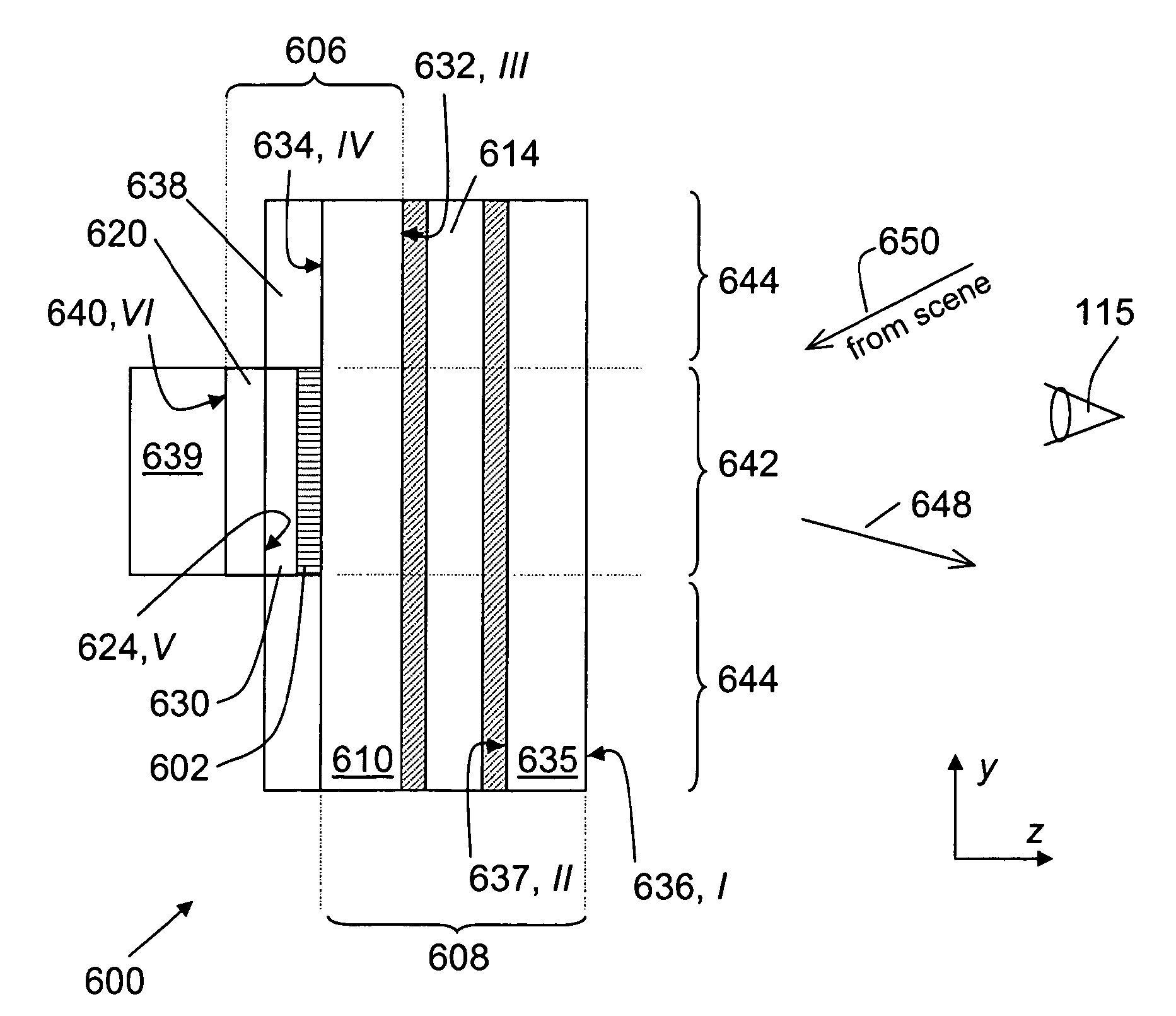
[0152]An example of such embodiment is illustrated in FIG. 34. As shown, the embodiment 3400 includes a TN LC-cell and an EC-cell. A switchable mirror system 3410 was fabricated as a combination of the EC-mirror element 840 (140 micron wide EC-chamber filled with EC-fluid)) and the TN LC-cell 3303 (LXD Inc., Cleveland, Ohio). The sample of the mirror system further included one APBF 3312 (DBEF-Q) laminated between the element 840 and the substrate 3304 of the LC-cell 3303 and another APBF 3311 (DBEF-Q) laminated between the LC-cell 3303 and the lite of glass 3315. The thickness of glass lites was approximately 1.6 mm. (Various optical coatings, electric connections, and housing elements necessary for proper operation of either the LC-cell or the EC-mirror element and discussed elsewhere in this application are not shown in FIG. 34 for simplicity of illustration.) The polarization axes of both polarizers 3311 and 3312 were aligned. When both the LC-cell 3303 and the EC-element 840 we...

example 2

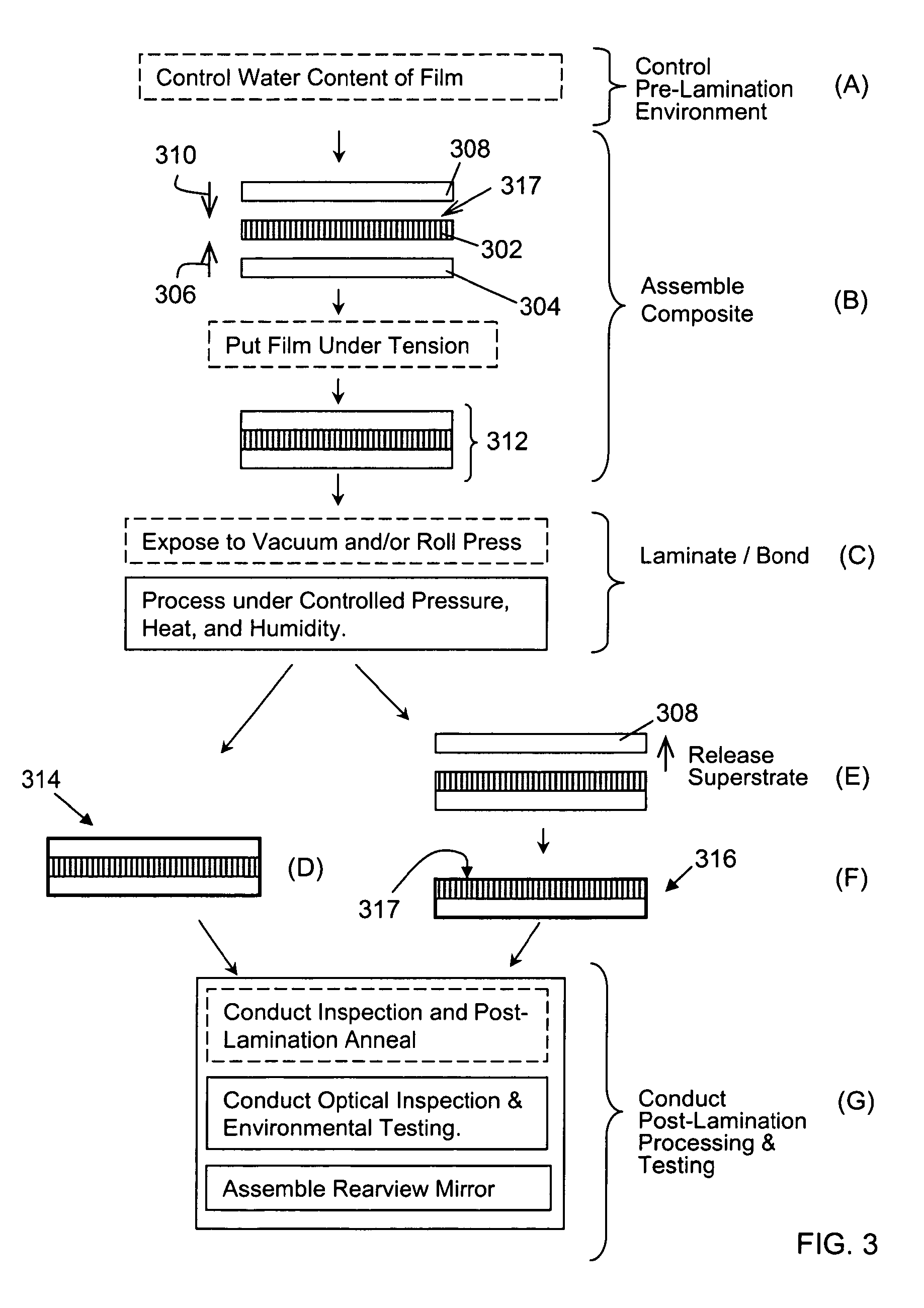
[0153]Another sample of the switchable mirror system was also fabricated according to the structure 3410, with polarization axes of the RPs 3311 and 3312 mutually aligned. The EC-element 840 included two glass substrates, each approximately 6 cm by 26 cm in size and 1.1 mm thick and carrying approximately 145 nm thick ITO electrode layers on the surfaces forming the EC-chamber. The EC-chamber of approximately 140 microns in width was assembled with the use of amine cure epoxy and filled with EC-fluid comprising 27 mM of the anodic material 5,10 dimethyl 5,10 dihydrophenazine and 32 mM of the cathodic material octylviologen tetrafluoroborate. The RPs 3311, 3312 were made of DBEF-Q sold by 3M Corp. of St. Paul, Minn. and flattened ad laminated according to the method of FIG. 3. The TN LC cell 3303 comprising two pieces of 1.1 mm glass was purchased from LXD Inc. of Cleveland, Ohio. The TN LC-cell based device was segmented, as described elsewhere in this application, to allow for inde...

example a

[0312]Table 23 lists design parameters of a thin-film stack on a glass substrate, while FIG. 38 shows a dispersion of reflectance and transmittance characteristics for this stack. The overall reflectance value for unpolarized light is about 35% in the visible range, while the transmittance nears zero below approximately 380 nm.


PUM

PropertyMeasurementUnit
pressureaaaaaaaaaa
pressureaaaaaaaaaa
temperatureaaaaaaaaaa

Abstract

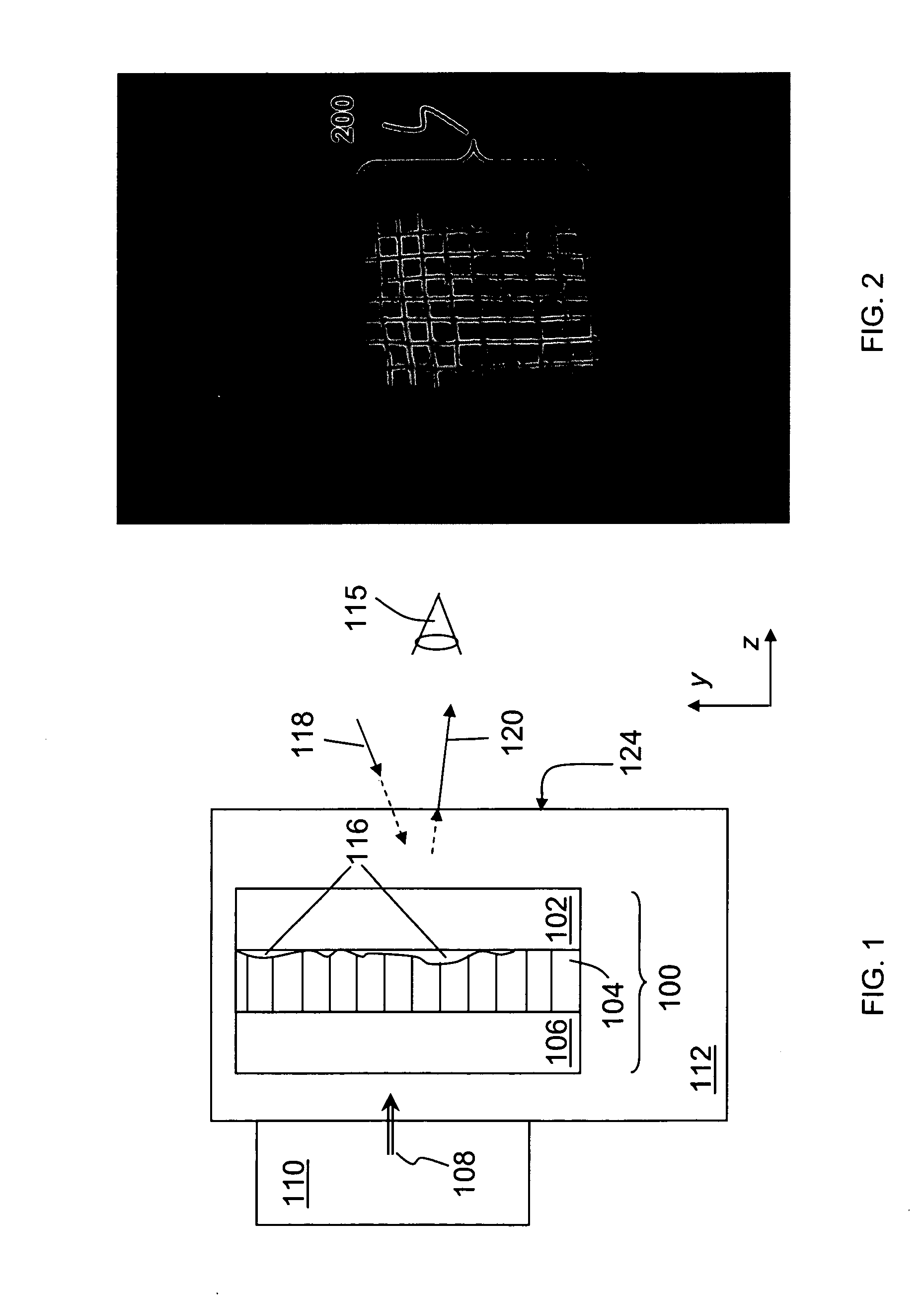
Anisotropic film laminates for use in image-preserving reflectors such as rearview automotive mirror assemblies, and related methods of fabrication. A film may comprise an anisotropic layer such as a light-polarizing layer and other functional layers. The film having controlled water content is heated under omnidirectional pressure and vacuum to a temperature substantially equal to or above a lower limit of a glass-transition temperature range of the film so as to be laminated to a substrate. The laminate is configured as part of a mirror structure so as to increase contrast of light produced by a light source positioned behind the mirror structure and transmitted through the mirror structure towards a viewer. The mirror structure is devoid of any extended distortion and is characterized by SW and LW values less than 3, more preferably less than 2, and most preferably less than 1.

Description

CROSS-REFERENCE TO RELATED APPLICATIONS[0001]The present application is a continuation-in-part of U.S. patent application Ser. No. 12 / 629,757 filed on Dec. 2, 2009, now U.S. Pat. No. 8,282,224, which is a continuation-in-part of U.S. patent application Ser. No. 12 / 496,620 filed on Jul. 1, 2009, now U.S. Pat. No. 8,545,030, which claims priority from U.S. Provisional Applications Nos. 61 / 079,668 filed on Jul. 10, 2008 and 61 / 093,608 filed on Sep. 2, 2008. The present application claims priority from each of the abovementioned applications. The disclosure of each of the above-mentioned applications is incorporated herein by reference in its entirety.TECHNICAL FIELD[0002]The present invention relates to polymer-based film laminates and, more particularly, to automotive rearview mirrors incorporating laminates comprising polymer-based film structures having an optically anisotropic layer.BACKGROUND ART[0003]Mirror assemblies have proven to be a convenient location for providing drivers ...

Claims


Application Information

Patent Timeline
Patent Type & Authority Patents(United States)
IPC IPC(8): G02B27/00B60R1/08G02B5/08G02F1/157G02B27/28G02F1/13G02B5/30G02F1/1516G02F1/1523
CPCB60R1/088G02B5/0816G02B27/28G02F1/157G02B5/3058G02F1/1313G02F2201/44G02F1/1516G02F1/1523G02F1/13725G02F1/133553G02F1/133357B60R1/12G02F1/0136G02F1/133536G02F1/13475G02F1/163
Inventor ANDERSON, JOHN S.TONAR, WILLIAM L.LUTEN, HENRY A.NEUMAN, GEORGE A.DOZEMAN, GARY J.MORGAN, TAMMY G.CAMMENGA, DAVID J.
Owner GENTEX CORP
Learn More