Tracking converters with input output linearization control

a technology of linearization control and tracking converter, which is applied in the direction of electric variable regulation, process and machine control, instruments, etc., can solve the problems of nonlinear operation of the control loop, difficult control of the system under these nonlinear effects, and transient problems

Active Publication Date: 2016-02-02
CIRASYS
View PDF52 Cites 3 Cited by
  • Summary
  • Abstract
  • Description
  • Claims
  • Application Information

AI Technical Summary

Problems solved by technology

Switching from one state to another during operation and the accompanying nonlinearity of power converters creates transient problems.
But, control of the system under these nonlinear effects becomes difficult when certain performance objectives must be met.
However, use of this method requires making several assumptions, one of them being so-called “small signal operation.” This works well for asymptotic stability in the neighborhood of the operating point, but ignores large signal effects which can result in nonlinear operation of the control loop when, for example, an amplifier saturates during startup, or during transient modes, such as load or input voltage changes.
Unstable zero dynamics associated with TEM with switch on-time sampling in the continuous conduction mode (“CCM”) prevent the use of an input-output feedback linearization because it would result in an unstable operating point for boost and buck-boost converters.
This makes control design extremely difficult.

Method used


Image

  • Tracking converters with input output linearization control
  • Tracking converters with input output linearization control
  • Tracking converters with input output linearization control

Examples


first embodiment

[0033]Referring to FIG. 2A, in a tracking inverter, a DC-AC tracking inverter converts a DC input voltage 201 to an AC output voltage 202 varying with time in a sinusoidal function.

second embodiment

[0034]Referring to FIG. 2B, in a tracking inverter, a tracking inverter function converts a DC input voltage 203 to an arbitrary time-varying output voltage 204 having an arbitrary waveform and arbitrary frequency spectrum.

third embodiment

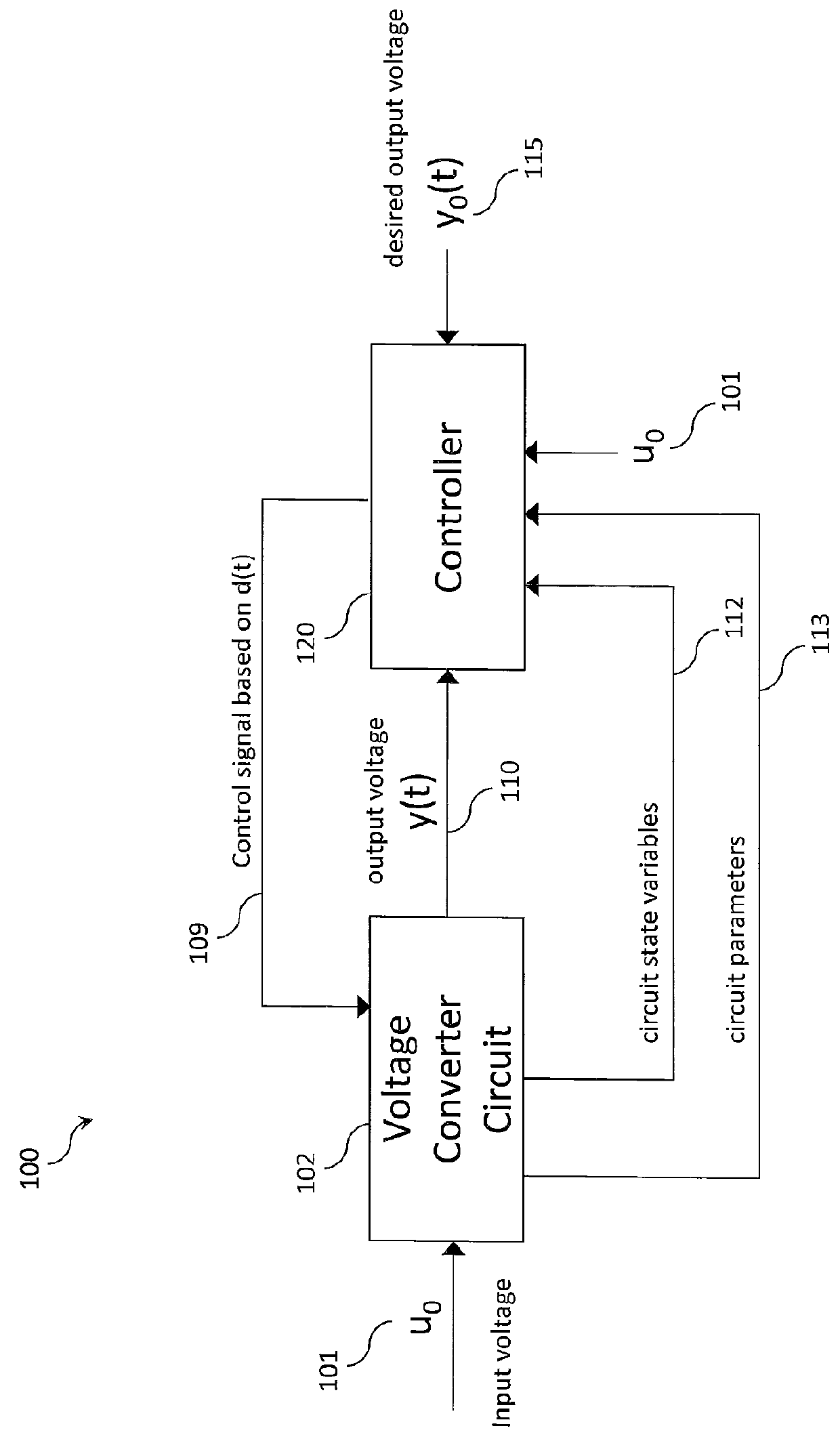
[0035]Referring to FIG. 2C, in a tracking inverter, a tracking inverter converts an AC input voltage 205 to an arbitrary time-varying output voltage 206. Further to FIG. 6C, the input voltage u0 may have an input waveform characterized by an input frequency while the output voltage y(t) may have an output waveform characterized by an output frequency. The output waveform can be different than the input waveform and the output frequency can be different than the input frequency. Moreover, the output frequency spectrum can be different that the input frequency spectrum for more complex waveforms.

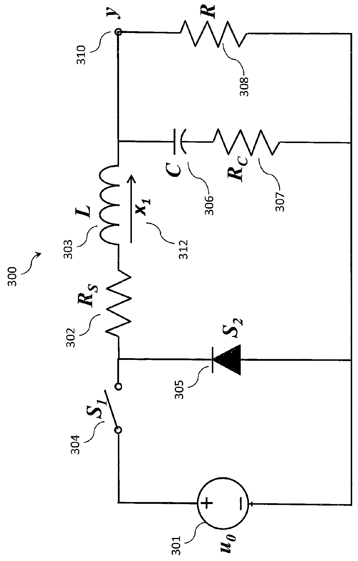
[0036]A theory of steady state tracking inversion is disclosed as follows. Voltage converter circuit 102 is characterized by a simple two dimensional linear system

{dot over (y)}=a11y+a12x1+b1d

{dot over (x)}=a21y+a22x1+b2d  Eq. 1

y=y

for state variables x1, output voltage y and control signal duty ratio d. It is assumed that the transfer function of Eq. 1 has no pole zero cancellations. The zer...


PUM


Abstract

In a preferred embodiment, a voltage inverter comprises a voltage converter circuit and a controller. The voltage inverter produces a time-varying output voltage from an input voltage, which can be a DC input voltage or an AC input voltage. The controller provides a control signal at a duty ratio determined dynamically by a set of signals. The set of signals include the time-varying output voltage, a predetermined output voltage, a gain factor and an inductor current in the voltage converter circuit. The predetermined output voltage can have an AC waveform or an arbitrary time-varying waveform. The voltage inverter operates to match the time-varying output voltage to the predetermined output voltage. Input-output linearization is used to design a buck inverter, and input-output linearization with leading edge modulation is used to design boost and buck-boost inverters under conditions where left half plane zero effects are present.

Description

CROSS-REFERENCE TO RELATED APPLICATIONS[0001]This application claims priority benefit from U.S. Provisional Application No. 61 / 670,520 filed Jul. 11, 2012. This application is a continuation-in-part of U.S. patent application Ser. No. 13 / 373,673 filed Nov. 22, 2011, which further claims priority benefit to U.S. Provisional Application No. 61 / 458,850 filed Dec. 2, 2010, which also is a continuation-in-part of U.S. patent application Ser. No. 12 / 487,242 filed Jun. 18, 2009.FIELD OF THE INVENTION[0002]The present invention relates generally to providing modulation signals to electrical circuits and, more particularly, to tracking inverters and tracking converters based on input-output linearization control.BACKGROUND OF THE INVENTION[0003]Power converters are used to convert one form of energy to another (e.g., AC to AC, AC to DC, DC to AC, and DC to DC) thereby making it usable to the end equipment, such as computers, automobiles, electronics, telecommunications, space systems and sat...

Claims


Application Information

Patent Timeline
Patent Type & Authority Patents(United States)
IPC IPC(8): H02M7/5395H02M3/158H02M3/156H02M1/00H03K7/08
CPCH02M7/5395H02M3/156H02M3/1582H02M3/158H02M2001/009H02M2001/0012H03K7/08H02M1/009H02M1/0012
Inventor HUNT, LOUIS, R.
Owner CIRASYS
Why Eureka
Try Eureka