Fuel cell system

a fuel cell and system technology, applied in the field of fuel cell systems, can solve the problems of reducing the concentration of hydrogen, reducing the power-generating capacity, and sometimes wasteful discharge of hydrogen, so as to reduce the concentration of fuel gas and prevent wasteful discharge of fuel

Active Publication Date: 2016-02-02
HONDA MOTOR CO LTD
View PDF3 Cites 0 Cited by
  • Summary
  • Abstract
  • Description
  • Claims
  • Application Information

AI Technical Summary

Benefits of technology

[0006]The present invention is conceived to solve the aforementioned conventional drawback, and an object thereof is to provide a fuel cell system capable of preventing wasteful discharge of fuel gas in a purging operation after starting up a fuel cell system.
[0008]Generally, an amount of water remaining in the fuel gas circulation path is different between an operation conducted after the replacement of the fuel gas with air and an operation which does not conduct such replacement previously. More specifically, since the amount of water remaining in the fuel gas circulation path is lower in the operation conducted after the replacement of the fuel gas with the air than the amount of water remaining in the fuel gas circulation path in the operation which does not conduct such replacement previously, concentration of the fuel gas in the fuel gas circulation path tends to be higher in the operation conducted after such replacement if the amount fluid discharged with water or hydrogen from the fuel gas circulation path is the same between the two cases. In the present invention, the amount of water included in the discharged fluid is decreased in the purging operation if a fewer amount of water remains in the fuel gas circulation path in accordance with the memory device memorizing whether inside the fuel gas circulation path is in the dry condition or the humid condition. That is, the present invention can prevent the concentration of the fuel gas discharged in periodical purging process from increasing after starting up the fuel cell system since the control unit controls the purge valve in such a manner that a fewer amount of fluid is discharged than the amount of discharged fluid in an ordinary state in which the replacement of the fuel gas with the air has not been conducted previously. Therefore, the present invention can prevent wasteful discharge of fuel in a purging operation.
[0009]In another aspect of the present invention, the control unit increases the amount of the fluid discharged from the fuel gas circulation path in such a manner that amount of fluid discharged in a fuel-gas-scavenge process is greater than the amount of fluid discharged in a water-scavenge process. In general, the amount of water remaining in the fuel gas circulation path after replacing the fuel gas with air (i.e., for diluting the fuel gas) is greater than the amount of water remaining in the fuel gas circulation path after replacing water with air. In this case, the present invention can prevent decreased concentration of fuel gas, which may be caused by insufficient purge in the fuel gas circulation path in periodical purging process after starting up the fuel cell system and replacing the hydrogen with air, by controlling the amount of fluid discharged with the fuel gas (hydrogen) to be greater than the amount of fluid discharged with water.
[0010]In another aspect, the control unit controls duration for opening the purge valve. Accordingly, the present invention can prevent an excessive increase of concentration of the fuel gas discharged from the fuel gas circulation path by reducing the amount of fluid discharged in periodical purging process after starting up the fuel cell system and after replacing the fuel gas with air, to be lower than that of a case not conducting such replacement.
[0011]The control unit may control a purge interval between a previous shut-off and a subsequent opening of the purge valve. Accordingly, the present invention can prevent an excessive increase of concentration of the fuel gas discharged from the fuel gas circulation path by extending the purge interval after a replacement of the fuel gas with air longer than the that of a case not conducting replacement.

Problems solved by technology

However, a fuel cell system having the hydrogen circulation path of this type has a problem that nitrogen and water permeating from a cathode into the hydrogen circulation path reduce the concentration of hydrogen and lower the power-generating capability; therefore, a purge valve provided in the hydrogen circulation path must be opened to prevent the reduction in the hydrogen concentration.
However, the conventional fuel cell system disclosed in the aforementioned Japanese publication has a problem that hydrogen would be discharged sometimes wastefully because the amount of circulated hydrogen is controlled by opening the purge valve.

Method used


Image

  • Fuel cell system
  • Fuel cell system
  • Fuel cell system

Examples


Embodiment Construction

[0016]The present invention can provide a fuel cell system capable of preventing wasteful discharge of fuel gas included in fluid discharged with water or fuel gas after starting up a fuel cell system.

[0017]Technical terms “purge” and “scavenge”, hereinafter used for explaining embodiments of the present invention, are defined as follows.

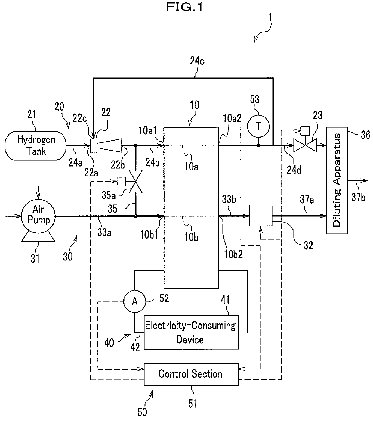
[0018]In the present specification, “purge” means discharging water, fuel gas, or mixture of them, from a fuel gas circulation path by introducing fuel gas into the fuel gas circulation path while maintaining an opening state of a purge valve; and “scavenge” means discharging water or fuel gas existing in a flow path including inside a fuel cell by introducing air into the flow path while maintaining an opening state of a purge valve.

[0019]Although an embodiment is explained with reference to vehicles including fuel-cell vehicles, the present invention is not limited to fuel cells used in vehicles and can be applied to any other fuel cells used for ...


PUM

PropertyMeasurementUnit
electric currentaaaaaaaaaa
temperatureaaaaaaaaaa
concentrationaaaaaaaaaa

Abstract

A fuel cell system calculates amount of fluid discharged from a fuel gas circulation path with water and fuel gas in accordance with an ordinary process map if inside an anode is not scavenged when a fuel cell stops electrochemical reaction; measures amount of water remaining in a fuel gas circulation path in accordance with cumulative electricity output, temperature, or elapsed time after starting the electrochemical reaction if the inside the anode is scavenged previously; and determines whether the inside the fuel gas circulation path is in dry condition or humid condition. The fuel cell system calculates amount of fluid discharged from the fuel gas circulation path with water or the fuel gas in accordance with a map predetermined for the dry condition if the fuel cell system determines that the inside the fuel gas circulation path is in the dry condition. The fuel cell system calculates the amount of the fluid to be discharged with the water or the fuel gas in accordance with the ordinary map if the fuel cell system determines that the inside the fuel gas circulation path is in the humid condition. Accordingly, wasteful discharge of fuel gas can be prevented in a purging operation after starting up the fuel cell system.

Description

CROSS-REFERENCE TO RELATED APPLICATIONS[0001]This application claims the foreign priority benefit under Title 35, United States Code, §119 (a)-(d), of Japanese Patent Application No. 2008-226883, filed on Sep. 4, 2008, in the Japan Patent Office, the disclosure of which is herein incorporated by reference in its entirety.BACKGROUND OF THE INVENTION[0002]The present invention relates to a fuel cell system having a purge valve for discharging impurities from a fuel gas circulation path.BACKGROUND ART[0003]Generally, in an attempt to use fuel gas effectively, a fuel cell system mounted on a fuel-cell vehicle or the like adopts a hydrogen circulation path through which hydrogen is supplied as a fuel gas to fuel cells, and the hydrogen unconsumed in the electro-chemical reaction, which is discharged from the fuel cell, is returned to the fuel cell again.[0004]However, a fuel cell system having the hydrogen circulation path of this type has a problem that nitrogen and water permeating fro...

Claims


Application Information

Patent Timeline
Patent Type & Authority Patents(United States)
IPC IPC(8): H01M8/04H01M8/06
CPCH01M8/0662H01M8/045H01M8/04231H01M8/04365H01M8/04589H01M8/04761H01M2250/20Y02E60/50Y02T90/32Y02T90/40
Inventor MIYATA, KOICHIRONAGOSHI, KENTAROUEHARA, JUNJIMATSUMOTO, YUJI
Owner HONDA MOTOR CO LTD
Why Eureka
Try Eureka