Radial input waveguide

a radial input waveguide and input waveguide technology, applied in the direction of instruments, frequency/directions obtaining arrangements, sound producing devices, etc., can solve the problems of long, complicated and expensive waveguides, large length of waveguides, etc., to increase acoustic power per unit area, increase the acoustic energy density, and increase the quality

Active Publication Date: 2016-01-26
DIMITROV DIMITAR KIRILOV
View PDF9 Cites 12 Cited by
  • Summary
  • Abstract
  • Description
  • Claims
  • Application Information

AI Technical Summary

Benefits of technology

[0024]Yet another object of the invention is to further drastically increase the high frequency supply in order to oppose the above mentioned phenomena by providing a way of further significantly increasing the acoustic energy density at the input of the high frequency line array element, i.e. stacking vertically a number of already horizontally stacked waveguide element groups, side by side in a vertical line, or in a slightly inclined line. This approach might enormously increase the acoustic power per unit area at the commonly united waveguide output, in comparison...

Problems solved by technology

One of the disadvantages in this prior art example is that expanding in axial direction in front of the driver, the length of the waveguide becomes relatively large.
Another, probably worse, disadvantage is that this axial expansion actually widens the air-passages along the way towards the middle of the guid...

Method used


Image

  • Radial input waveguide
  • Radial input waveguide
  • Radial input waveguide

Examples


Embodiment Construction

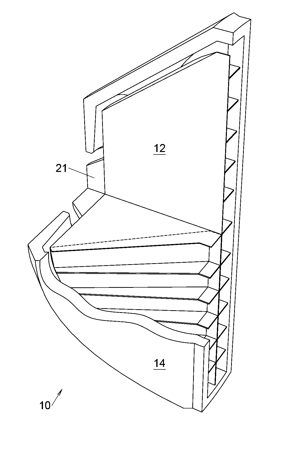
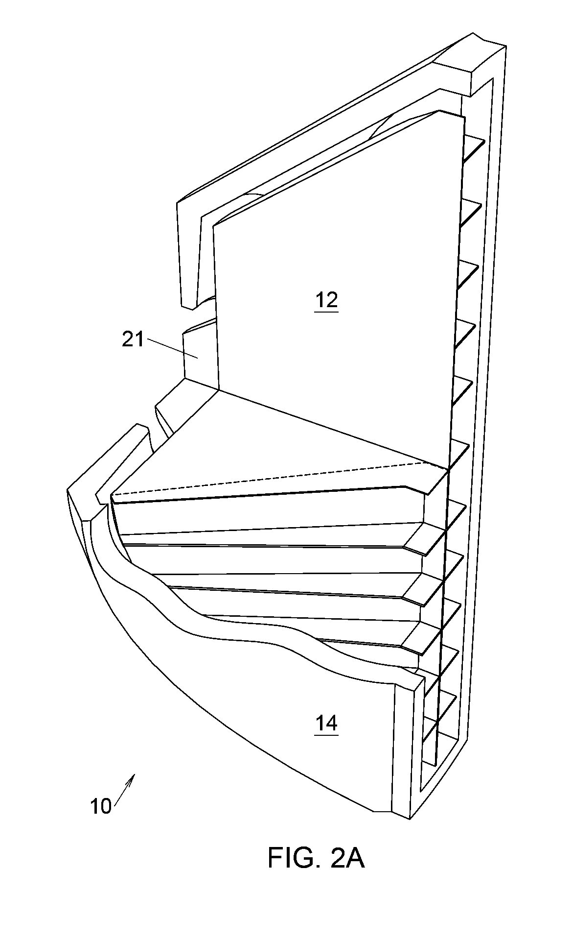
[0087]For better understanding of the gist of the radial-input waveguide, a number of basic elementary surfaces are used to illustrate how the waveguide walls are generated. The walls restrict an air channel, or a plurality of individual air channels, guiding sound wave propagation from a compression driver output to the waveguide output. FIG. 2A illustrates a principal waveguide 10, consisting of internal body 12 which is enclosed by shell 14 at a distance. To the waveguide input, an appropriate compression driver 15 is firmly attached. In FIG. 3B all generatrix surfaces 13, forming the walls between which sound waves propagates, are pictured on its uppermost left side. They form an internal body 12, shell internal walls 20b, 24b and 29b, and an air channel 16 positioned between shell 14 and the internal body 12. Air channel 16 consists of three consecutive virtual passageway elements 16a, 16b and 16c, all shown as exploded perspective view in FIG. 3C.

[0088]Two vertical and substan...


PUM


Abstract

Radial input waveguide is provided having three consecutive sound wave propagation passageways, virtually divided by two folding regions along its extension from radial input up to substantially rectangular output, each one forming a different type of waves and all three channels shaped between an internal body and a shell housing enclosing it at a distance. The radially expanding initial air channel forms a cylindrical wave front between two input walls. A relatively wide region with parallel walls is available for wave folding at adaptably changeable diameters in this region with a small distance between the folded walls. All individual partial wave fronts on the periphery of the first folding region are traveling along substantially equal, accumulated from the last two air channels, path lengths, to the waveguide output, forming there a common isophase and planar wave front. The middle passageway contains all the physical dimensions necessary to control the waveguide performance, the most important being the height H and the width D, whose ratio controls the wave front output curvature.

Description

BACKGROUND[0001]Waveguides are commonly referred to as “acoustical transformers” transforming the acoustical impedance from a horn input to the compression driver output. The current invention is to be implemented in line array systems as a transition element between the compression driver output and the high frequency line-array input, usually a rectangular vertical area band, very narrow in a horizontal plane, which makes possible fast horn flares opening, thus defining a relatively wide horizontal coverage. The vertical directivity of a line array system is typically realized by aligning such horns as close as possible to each other in a vertical line or in a slightly curved line, in both cases trying to simulate a cylindrical or prolate spheroidal wave front of the line array group up to the highest audible frequencies. To achieve this, all individual wave front outputs must be in-phase, all the way from top to bottom along its height, in order to create a coherent common wave f...

Claims


Application Information

Patent Timeline
IPC IPC(8): G10K13/00G10K11/02
CPCG10K11/22G10K11/26H04R1/30H04R1/345H04R1/403H04R2201/34H04R2400/13
Inventor DIMITROV, DIMITAR, KIRILOV
Owner DIMITROV DIMITAR KIRILOV
Why Eureka
Try Eureka