Arrangement and method for manufacturing can lids

a technology for can lids and can lids, which is applied in the field of can lid arrangement and a manufacturing method, can solve the problems of limited operating life of the rib, deterioration of the quality of the stamping rib, and the quality of the tear notch of the can lid, so as to reduce the mechanical wear of the press tool and the press mold, improve the service life, and improve the effect of quality

Inactive Publication Date: 2016-01-26
SCHULER PRESSEN GMBH & CO KG
View PDF11 Cites 0 Cited by
  • Summary
  • Abstract
  • Description
  • Claims
  • Application Information

AI Technical Summary

Benefits of technology

[0005]The object is solved by a method according to claim 1 and a stamping tool according to claim 8. The method according to the invention is for the manufacture of tear notches (22) in can lids (11), the can lid (11) is subjected in the press tool (10) to a laser engraving during which the desired tear notch (22) is generated. The laser ablation process occurs preferably, with the press tool (10) closed, within a time period of less than 30 ms (milliseconds). During this time, the focal spot (27) of the laser beam (26) is moved over the whole desired contour of the tear notch (22) so that an uninterrupted groove-like cavity is formed. With the use of laser engraving in the press tool, the mechanical wear of the press tool and of the press molds can be minimized and in this way the tool operating life can be increased. In particular, the manufacture of can lids with consistently high quality is ensured.
[0007]With the forming of the tear notch as a laser engraving the quality of the can lids formed and particularly of the tear notch remains uniform independently of the number of can lids already produced earlier. The tool wear which, because of the wear of the relatively sensitive stamping rib for the forming of the tear notch is normally determined by the stamping rib, and is therefore reduced.
[0008]The manufacture of the tear notch in the form of a laser engraving reduces also the stress of the stamping tool. While the conventional manufacture of the tear notch during the stamping procedure requires a high press load at the lower dead center, the laser engraving occurs without any load on the press. This tool no longer needs to move during the stamping step against a fixed stop, that is a solid wall. The bearing loads of the press and the elastic press deformation are reduced and the operating smoothness is improved. Presses may be used which are designed for much lower maximum forces.
[0011]Whereas a stamped tear notch is formed by a displacement of material, the laser engraved tear notch is formed by material removal. With a predetermined control of the heat input and, possibly, a predetermined cooling by a gas or air jet applied to the laser treatment side or to the side opposite the laser treatment of the can lid, the material structure along the tear notch may be changed in addition to the material removal. The structural change can be so controlled that the hardness of the can material in the tear notch area is increased whereby, on one hand, higher rigidity but also an increased brittleness is obtained which improves the tearing capability.
[0013]It is considered to be expedient to design the forming station of the tool in which the laser engraving occurs in such a way that the material of the lid is firmly engaged in the proximity of the tear notch to be generated between corresponding pressure surfaces of the tool. In this way, the position of the can lid with regard to the direction of the laser beam is accurately fixed. The laser beam can therefore operate with a short focus range. In addition, it is possible with the precise positioning of the lid to form the tear notch with the desired cross-sectional shape, in particular with rounded flanks. In particular if the tear notch is disposed on the outside of the can lid sharp edges of the tear notch facing the later user of the can are generally avoided.
[0014]The press tool according to the invention includes a laser head which includes means for moving the laser focus spot along the contour of the tear line to be generated upon opening of the can lid. The operation of the laser head is synchronized with the opening and closing of the press tool. Preferably, the synchronization is so selected that the means (drive) by which the laser focus spot is moved along the desired contour is operating only when the press tool is at rest. In connection with presses and press tools which run particularly fast, for example, a resiliently supported lever or holder may be provided which, at the engraving stage, contacts the can lid already before the lower dead center is reached by the movable press part and which holds the can lid in engagement with the stationary tool part already while the press plunger is still moving. Such an arrangement gains some time for performing the laser engraving.

Problems solved by technology

The rib, however, has a limited operating life.
With increasing wear of the stamping rib the quality of the stamping rib deteriorates and so does the quality of the tear notch of the can lid manufactured thereby until it becomes unacceptable.

Method used


Image

  • Arrangement and method for manufacturing can lids
  • Arrangement and method for manufacturing can lids
  • Arrangement and method for manufacturing can lids

Examples


Embodiment Construction

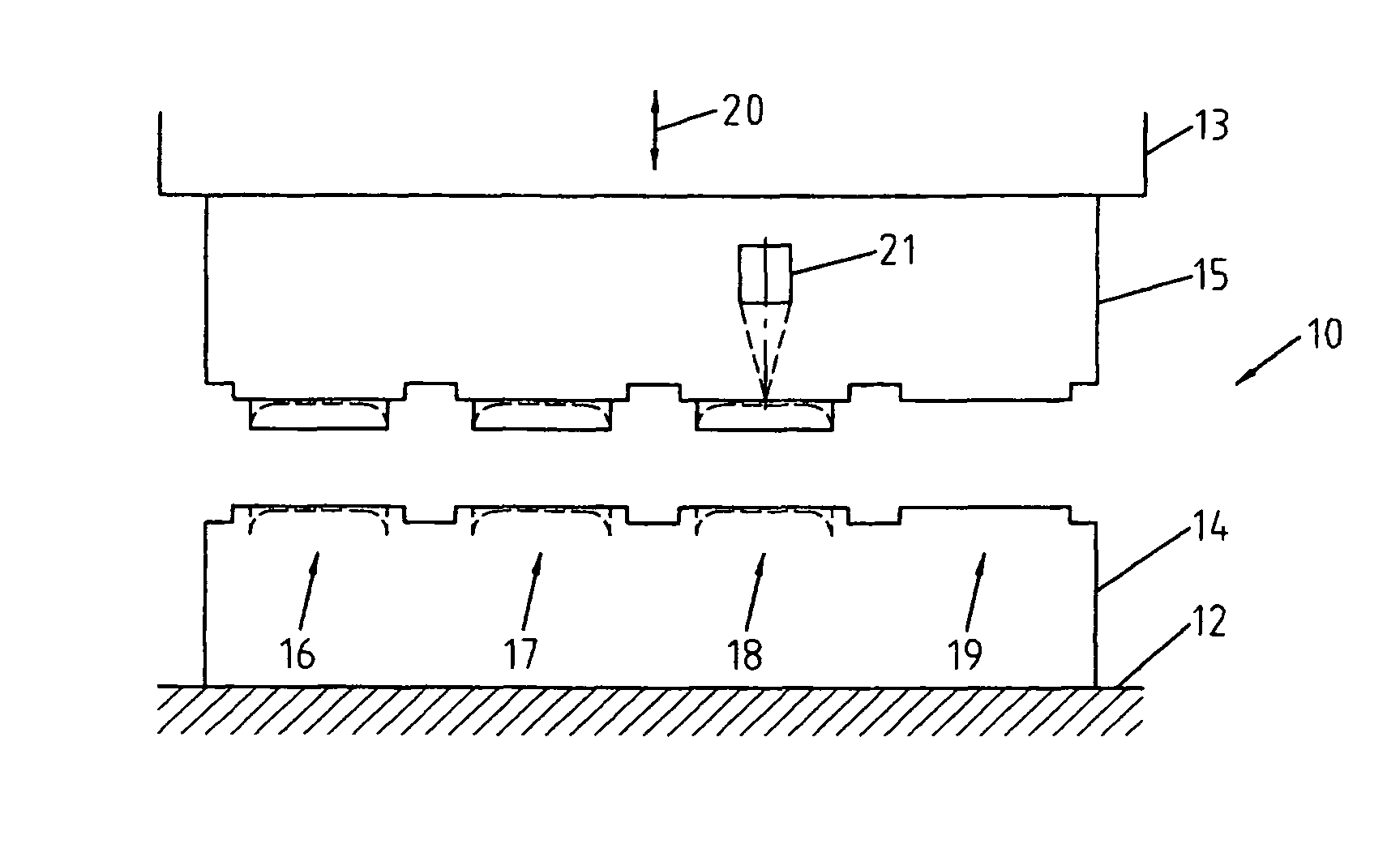
[0033]FIG. 1 shows a press tool 10 for the manufacture of can lids 11 of which one is shown schematically, for example, in FIG. 3. The press or deformation tool 10 is arranged, for example, in a press between a press table 12 and a plunger 13. It comprises a first or lower tool part 14 as well as a second or upper tool part 15. The press tool 10 is preferably a stepping tool with several forming stages 16, 17, 18, 19. These tool stages are provided for different forming operations which are required to form from a planar metal sheet the desired can lid 11 as it is shown, for example, in FIGS. 5 and 7 in vertical sectional view or respectively in a top view. FIGS. 3, 5 and 7 show each an exemplary embodiment of a lid of a beverage can, however, also other can lids as, for example, for canned fish cans can be manufactured according to the invention in the press tool 11.

[0034]In the individual tool stages 16-19 in the lower tool part 14 and in the upper tool part 15 respective compleme...


PUM

PropertyMeasurementUnit
time periodaaaaaaaaaa
timeaaaaaaaaaa
brittlenessaaaaaaaaaa

Abstract

In a method according to the invention for the manufacture of tear notches (22) in can lids (11), the can lid (11) is subjected in the press tool (10) to a laser engraving during which the desired tear notch (22) is generated. The laser ablation process occurs preferably, with the press tool (10) closed, within a time period of less than 30 ms. During this time, the focal spot (27) of the laser beam (26) is moved over the whole desired contour of the tear notch (22) so that an uninterrupted groove-like cavity is formed. With the use of laser engraving in the press tool, the mechanical wear of the press tool and of the press molds can be minimized and in this way the tool operating life can be increased. In particular, the manufacture of can lids with consistently high quality is ensured.

Description

CROSS-REFERENCE TO RELATED APPLICATION[0001]This application claims the priority of German Application No. 10 2010 037 951.4-14 filed Oct. 4, 2010.BACKGROUND OF THE INVENTION[0002]The invention resides in an arrangement and a method for the manufacture of can covers, in particular beverage can lids. Typically beverage cans and also other food cans are covered at their top by a lid which can easily be ripped open by hand along a tear notch. The tear notch is formed during the manufacture of the can lid by material displacement, for example, during a stamping step. The respective tear notch has still a strength sufficient to safely prevent unintended opening of the lid. On the other hand, a local tension concentration is generated when a butt strap attached to the lid is lifted and the lid is pulled away thereby. The tear notch forms a desired breaking path along which the lid can be opened with a relatively low force.[0003]The stamping of tear notches in can lids requires high-qualit...

Claims


Application Information

Patent Timeline
Patent Type & Authority Patents(United States)
IPC IPC(8): B21D51/38B21D51/44B23K26/00B65D17/00
CPCB21D51/383B21D51/443B23K26/0093B23K26/364B65D17/24B23K2201/125B65D17/404B23K2101/125
Inventor BLEI, KLAUSROVER, MARKUS
Owner SCHULER PRESSEN GMBH & CO KG
Why Eureka
Try Eureka