
Dental shaping strip

a technology of dental shaping and strip, applied in the field of dental shaping strip, can solve the problems of not allowing food, premature failure, and difficulty in placing composite restorations properly, and achieve the effect of not diminishing the tightness of the contact area

Active Publication Date: 2016-01-19
VAN PUTTEN CLIFFORD JOHN
View PDF29 Cites 2 Cited by
  • Summary
  • Abstract
  • Description
  • Claims
  • Application Information

AI Technical Summary

Benefits of technology

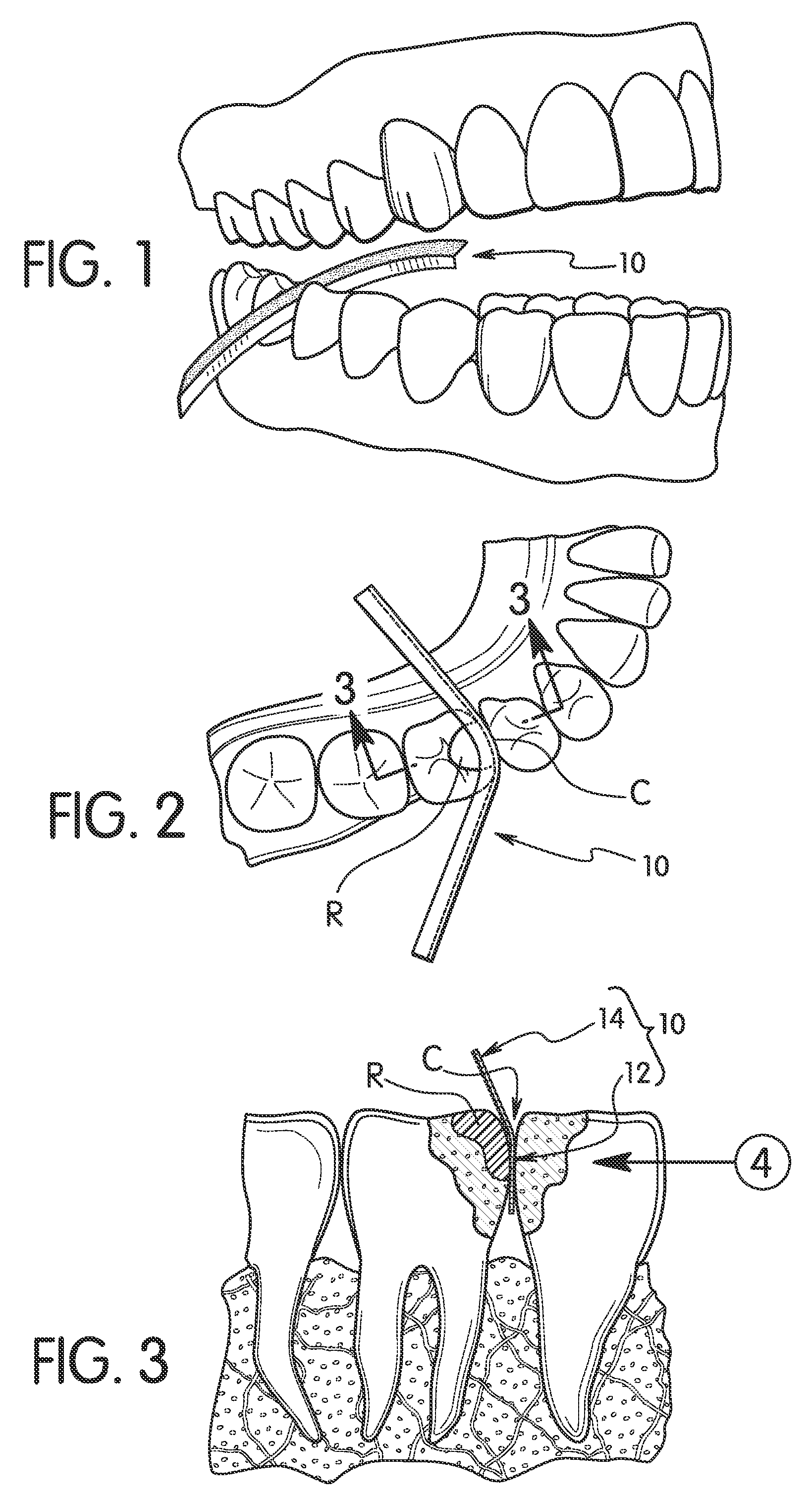
[0007]Occlusal to the contact area is the occlusal embrasure. The occlusal embrasure takes the shape of a “V” between adjacent posterior teeth. This “V” or occlusal embrasure does not allow food to be compacted into the contact area. As the tooth surface diverges from the contact area toward the biting or occlusal surface, the tooth surface forms an elevated linear ridge called the marginal ridge. The marginal ridge is shaped like a hill or buttress. In unworn dentition, the height of the marginal ridge is not directly above the contact area. Instead, in unworn dentition, the height of the marginal ridge is always more toward the center of the tooth. God designed (shaped and positioned) this hill or buttress to reinforce and to impart strength to the tooth. The marginal ridge bears the forces of mastication. Although enamel generates sufficiently high compressive strength, enamel exhibits low tensile strength. Therefore, the marginal ridge is a rounded surface, with no sharp bends or corners. God has designed the marginal ridge in this manner because sharp bends and corners of enamel are prone to fracturing and chipping, e.g., due to tensile stresses that would be applied thereto. Also, the rounded surfaces of the occlusal embrasures are more self-cleansing than if the surfaces of the teeth had angles or corners where food could become entrapped.
[0020]Yet another object of the present disclosure is to provide a dental shaping strip that mikes it possible to shape the composite dental restoration to match a shape of a natural tooth (e.g., to have a rounded marginal ridge), i.e., without sharp bends or corners and without a tabletop structure.

Problems solved by technology

It has been discovered that, despite the popularity of composite restorations, there are challenges to placing composite restorations properly.
Improperly shaped restorations with sharp edges and corners will chip and fracture, resulting in premature failure.
This “V” or occlusal embrasure does not allow food to be compacted into the contact area.
Although enamel generates sufficiently high compressive strength, enamel exhibits low tensile strength.
Light or open contacts fail to protect the interdental gingival tissue from the forces of mastication, meaning that food could slip through the light or open contact area and become wedged into the interdental papilla.
Such food impaction could initiate a chain of events resulting in decay, periodontal destruction, and pain.
A current daily challenge in clinical restorative dentistry is replacing tooth tissue by placing a composite resin bonded restoration between two teeth, usually because of decay.
However, currently, there is no good technique for developing the “V” shaped occlusal embrasure.
Unfortunately, this technique suffers from poor control, digging into the restoration and likely iatrogenic damage to the adjacent tooth.
In particular, the problem with the current technique is the shaping and smoothing of the occlusal embrasure of a composite restoration to match that of a natural tooth.
Such tabletop restorations have sharp, unsupported edges that are weak and may succumb to fracture and chipping.
Sharp angles or corners that are incorporated into an interproximal restoration also present a greater oral hygiene challenge for the patient, as sharp edges can snag and shred floss.
However, clinically (in practice) it is a very difficult task to form a fossa, marginal ridge and occlusal embrasure prior to photo activation.
However, using rotary instruments after curing results in the problem of digging into or damaging both the new restoration and the adjacent tooth as mentioned above.
While many devices have been designed or created to shape and smooth the interproximal surface or the contact area, none of these devices meets the need for shaping the occlusal embrasure area.

Method used


Image

  • Dental shaping strip
  • Dental shaping strip
  • Dental shaping strip

Examples


second embodiment

[0063]Referring now to FIG. 16-18, a dental shaping strip 210 in accordance with a second embodiment will now be explained. In view of the similarity between the first and second embodiments, the parts of the second embodiment that are identical to the parts of the first embodiment will be given the same reference numerals as the parts of the first embodiment. Moreover, the descriptions of the parts of the second embodiment that are identical to the parts of the first embodiment may be omitted for the sake of brevity. In other words, the descriptions and illustrations of the first embodiment also apply to this second embodiment, except as explained and illustrated herein. Furthermore, it will be apparent from this disclosure that parts of this embodiment that are identical or functionally identical will be given the same reference numerals as the first embodiment but with “200” added thereto.

[0064]The dental shaping strip 210 is identical to the shaping strip 10 of the first embodim...


PUM


Abstract

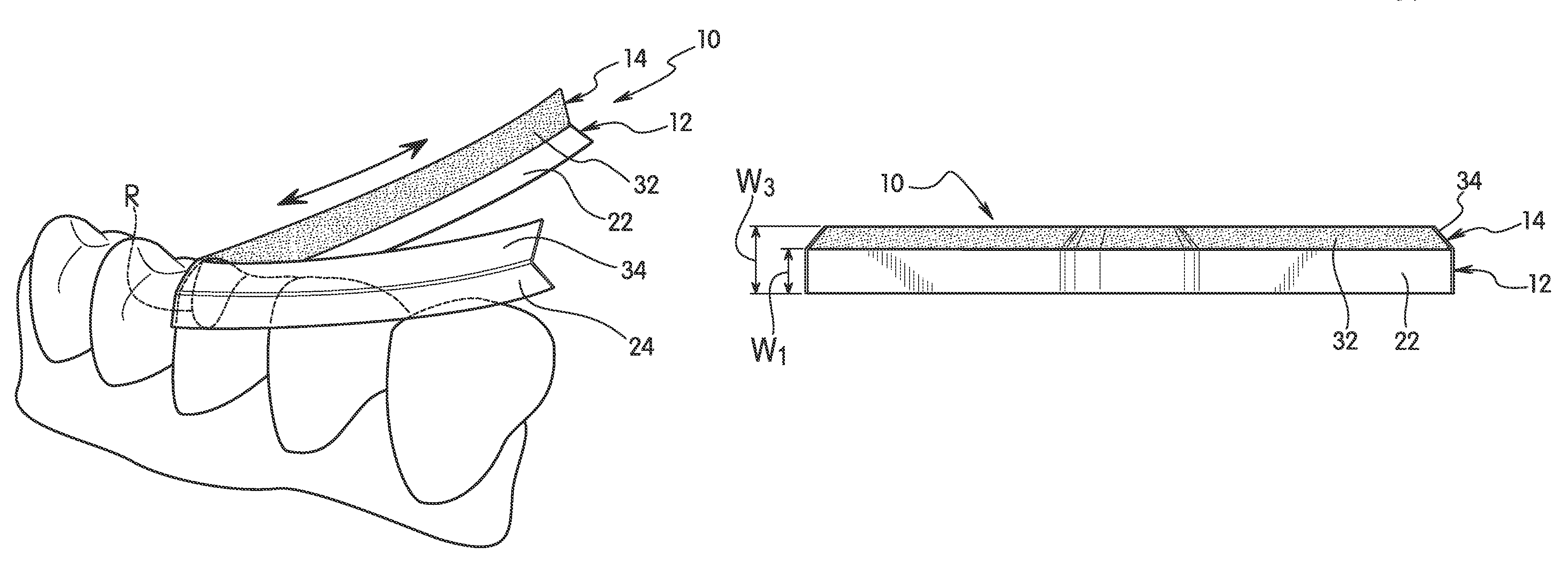
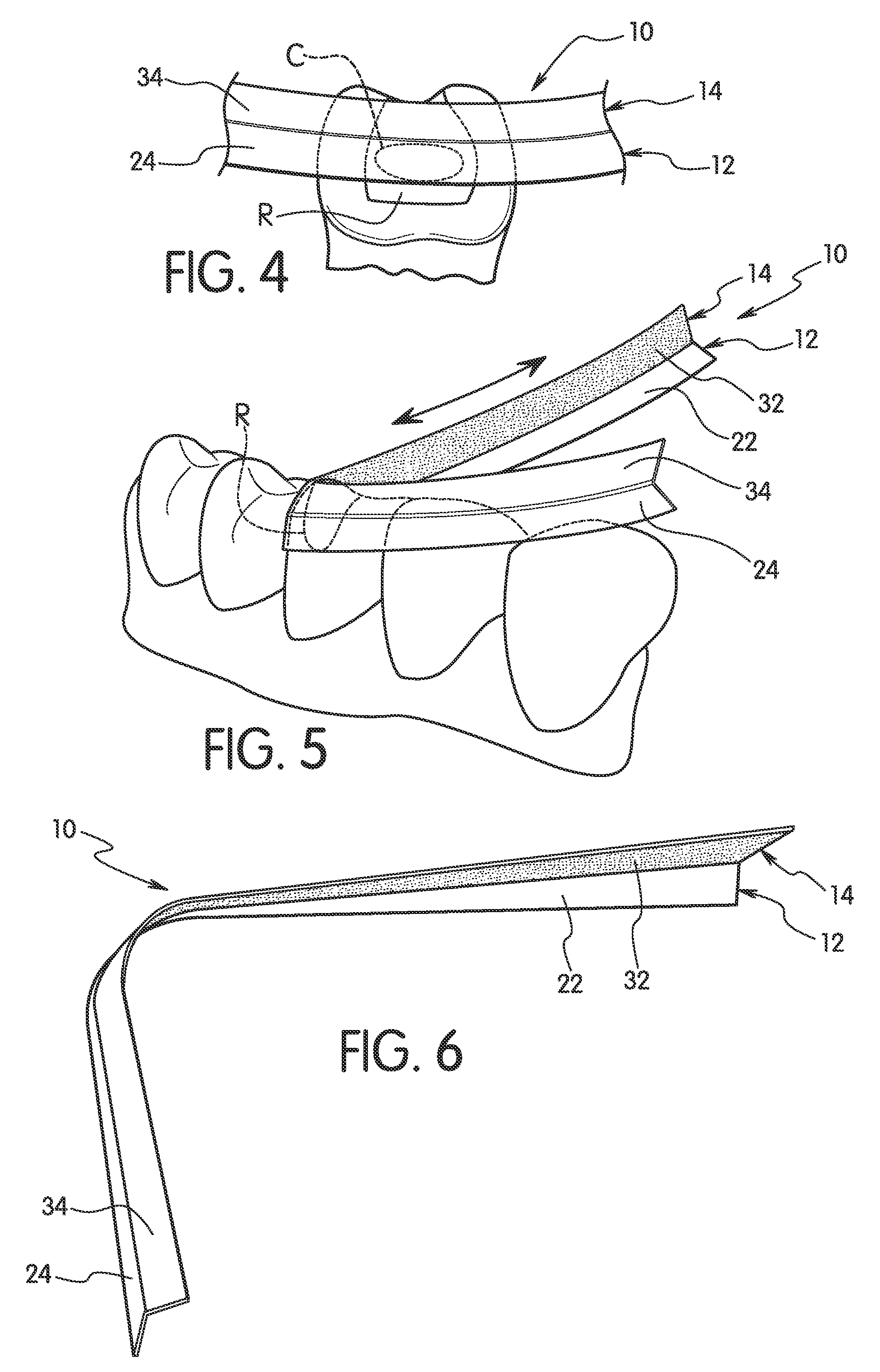
A dental shaping strip includes a base portion and a shaping portion. The base portion has a first base surface and a second base surface facing in an opposite direction from the first base surface. The first and second base surfaces have prescribed longitudinal lengths and prescribed widths transverse to the prescribed longitudinal lengths. The shaping portion is connected to a longitudinal edge of the base portion. The shaping portion has a first shaping surface connected to the first base surface, with at least part of the first shaping surface being abrasive. The first and second base surfaces are at least partially non-abrasive. Preferably, the first shaping surface and the first base surface diverge from each other as they approach longitudinal free edges of the dental shaping strip. Preferably, the first and second base surfaces are non-abrasive along their prescribed longitudinal lengths.

Description

BACKGROUND[0001]1. Field of the Invention[0002]The present invention generally relates to a dental shaping strip. More specifically, the present invention relates to a dental shaping strip with a non-abrasive portion and an abrasive portion.[0003]2. Background Information[0004]Metal fillings were regularly used to fill openings in teeth, such as openings caused by tooth decay (cavities), from the 19th century. In recent years, non-metallic materials have been used to fill openings in teeth. Currently, the most common material used to fill interproximal restorations in posterior teeth is resin based composite.SUMMARY[0005]It has been discovered that, despite the popularity of composite restorations, there are challenges to placing composite restorations properly. Improperly shaped restorations with sharp edges and corners will chip and fracture, resulting in premature failure. Properly placed resin based composite restorations will duplicate the embrasures, contact area, marginal rid...

Claims


Application Information

Patent Timeline
Patent Type & Authority Patents(United States)
IPC IPC(8): A61C3/06A61C5/12A61C5/04
CPCA61C3/06A61C5/04A61C5/125A61C5/50A61C5/85
Inventor VAN, PUTTEN, CLIFFORD, JOHN
Owner VAN PUTTEN CLIFFORD JOHN
Learn More