
Methods for adjusting the position of a main coil in a cyclotron

a cyclotron and main coil technology, applied in the field of cyclotrons, can solve the problems of adding complexity and cost, negatively affecting the accuracy of the method, so as to improve the accuracy of lateral positioning and good sensitivity

Active Publication Date: 2016-01-12
ION BEAM APPL
View PDF2 Cites 19 Cited by
  • Summary
  • Abstract
  • Description
  • Claims
  • Application Information

AI Technical Summary

Benefits of technology

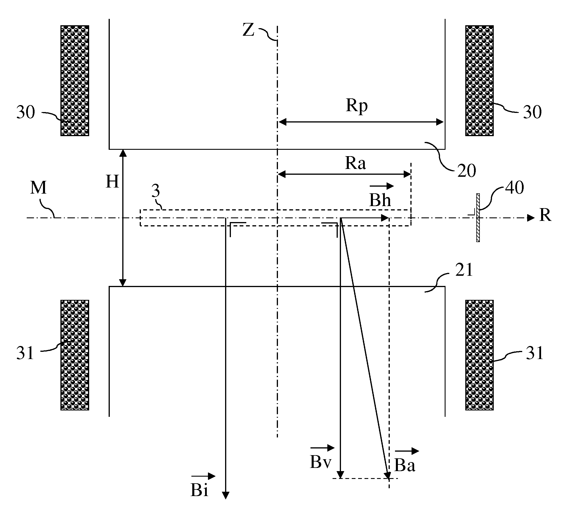
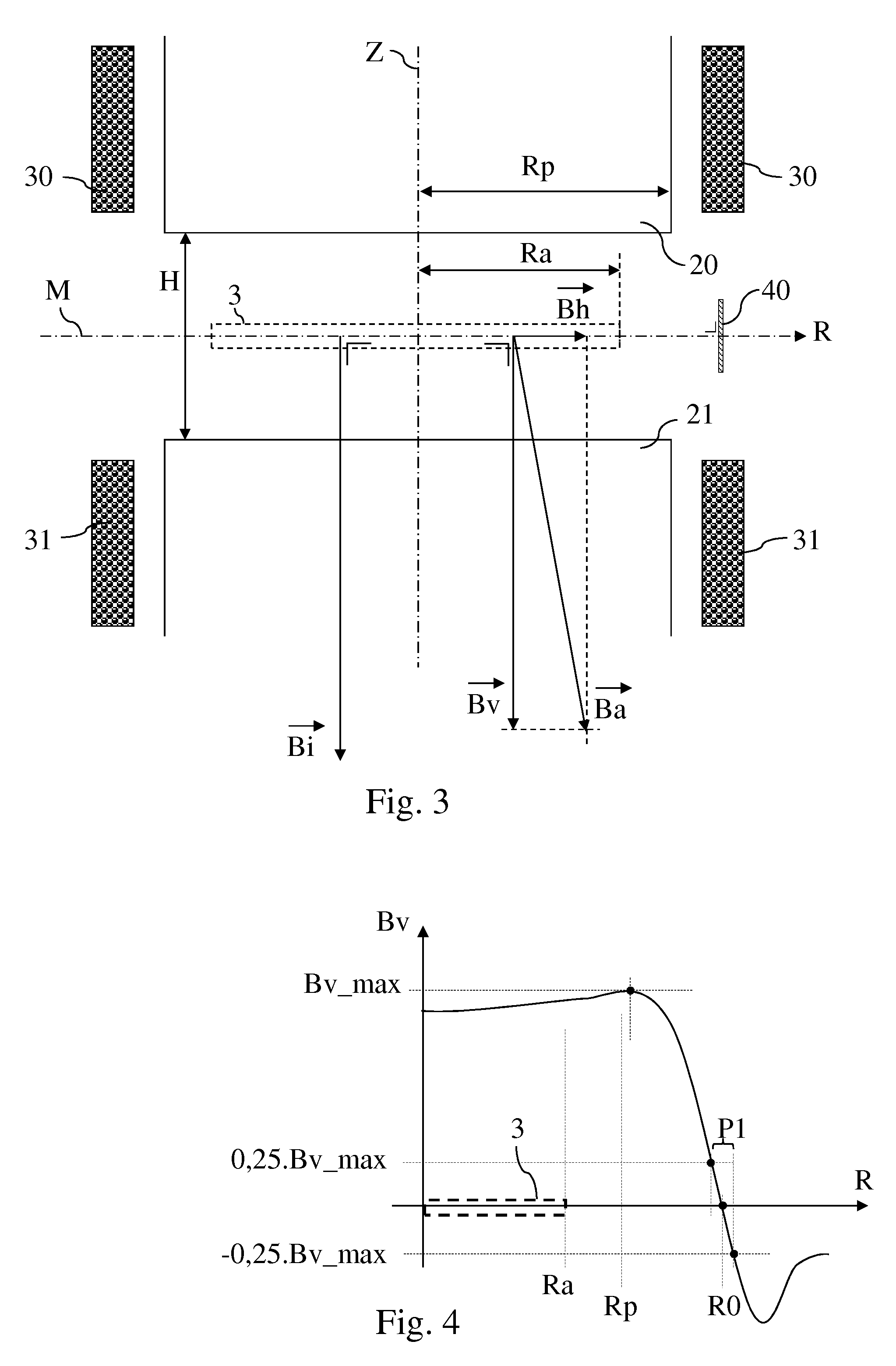
The invention provides methods for improving the accuracy of positioning a main coil assembly in a cyclotron with respect to the median plane and the central axis. The methods involve measuring the magnetic field in the particle acceleration region and adjusting the position of the main coil assembly to reduce the measured magnitude. By doing so, the accuracy of the magnetic field is less affected by misalignment of the magnetic field sensor. Additionally, the methods also involve adjusting the position of the main coil assembly based on magnetic field amplitudes at radial positions outside the particle acceleration region, to achieve better sensitivity and lateral positioning accuracy.

Problems solved by technology

A problem with such a method is that any asymmetry in the magnetic circuit will negatively influence the accuracy of the method.
Another problem is that it requires sensors and related equipment for measuring the forces in all the support links, which adds complexity and cost.
Yet another problem is that it is an indirect method, which may also negatively influence its accuracy.
Indeed, when the main coil assembly is misaligned, charged particles will move out of their desired trajectory and will be lost, so that the efficiency of the cyclotron will drop and vice-versa.
A problem with this method is that the efficiency may be influenced by other parameters than the position of the main coil assembly, so that this method is not accurate enough.

Method used


Image

  • Methods for adjusting the position of a main coil in a cyclotron
  • Methods for adjusting the position of a main coil in a cyclotron
  • Methods for adjusting the position of a main coil in a cyclotron

Examples


Embodiment Construction

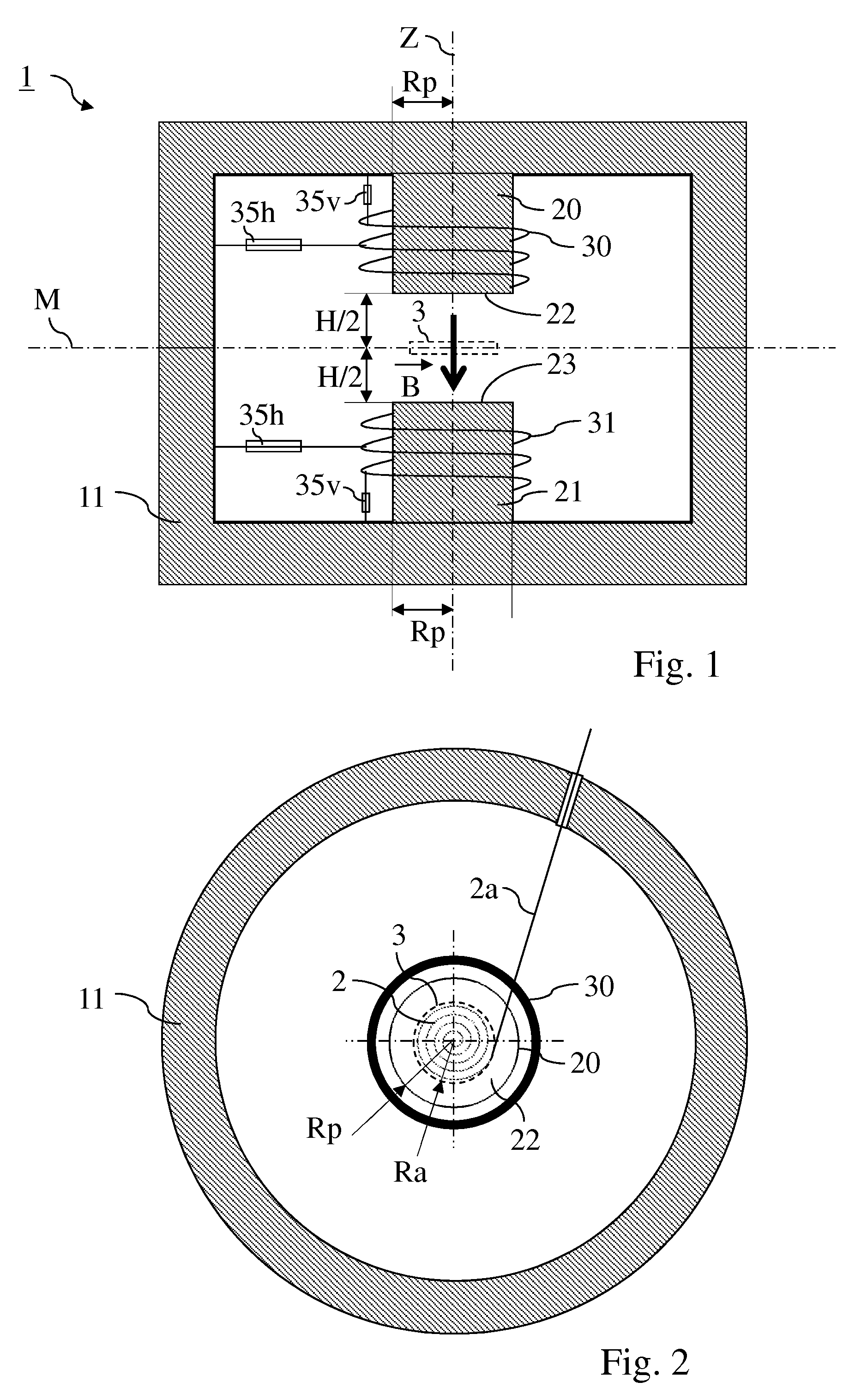
[0045]FIG. 1 schematically shows the main magnetic parts of an exemplary cyclotron (1), which include a main magnetic circuit comprising a main magnetic core (11) presenting two protruding poles (20, 21), whose respective distal faces (22, 23) are facing each other, and an outer return path for the magnetic field. Although not shown on this figure, the gap between those two distal faces is equipped with acceleration electrodes (sometimes called “dees”) which are designed to generate an electric field which, when in operation, will accelerate the charged particles in a particle acceleration region (3) around a median plane (M) of the cyclotron (1) until said particles are extracted from the cyclotron (1) for further use.

[0046]A main coil assembly (30, 31) is mounted around the two poles (20, 21) and is adapted, when exited, to generate a main magnetic field ({right arrow over (B)}) in the particle acceleration region (3). In order to keep the charged particles in a desired trajectory...


PUM


Abstract

The invention concerns methods for adjusting the position of a main coil assembly in a cyclotron with respect to a median plane (M) and / or to a central axis (Z) of the cyclotron.

Description

CROSS-REFERENCE TO RELATED APPLICATIONS[0001]This application claims the benefit of priority of European Application No. 13170532.9, filed Jun. 4, 2013, the disclosure of which is hereby incorporated by reference herein in its entirety.FIELD OF THE INVENTION[0002]The invention relates to the field of cyclotrons and to methods for adjusting the position within the cyclotron of a main magnetic field generating coil assembly.BACKGROUND OF THE INVENTION[0003]A cyclotron is a type of particle accelerators which comprise a vacuum enclosure in which charged particles are accelerated outwards from a central axis and along a spiral trajectory in an acceleration region of a median plane of the cyclotron under the combined effect of a high frequency electric field ({right arrow over (E)}) and of a main magnetic field ({right arrow over (B)}), the latter being generated by excitation of a main coil assembly.[0004]It is known that the main magnetic field ({right arrow over (B)}) has to be orient...

Claims


Application Information

Patent Timeline
Patent Type & Authority Patents(United States)
IPC IPC(8): H05H13/00
CPCH05H13/005
Inventor KLEEVEN, WILLEM, JAN, G.
Owner ION BEAM APPL
Learn More