LED lighting fixture

a technology of led light fixtures and led modules, which is applied in the field of light fixtures, can solve the problems of heat dissipation and the particular challenges of high-luminance led light fixtures using led modules as light sources, and achieve the effects of small aperture, better clearance, and small apertur

Active Publication Date: 2015-12-29
IDEAL IND LIGHTING LLC
View PDF96 Cites 3 Cited by
  • Summary
  • Abstract
  • Description
  • Claims
  • Application Information

AI Technical Summary

Benefits of technology

[0012]The central portion may have a plurality of fins protruding in a direction opposite the LED illuminator. In some of such embodiments, the heat sink includes at least one central-portion opening facilitating ambient-fluid flow to and from the heat-dissipating surfaces of the central portion. The fins of the central portion may define between-fin channels open at the front ends of such fins. In some embodiments, the rear ends of such fins are configured to permit ambient-fluid flow (e.g., water drainage) from the between-fin channels to the at least one central-portion opening, thereby facilitating liquid drainage therefrom. The at least one central-portion opening may be adjacent to the enclosure.
[0013]In some embodiments, the LED-supporting region of the heat sink has a surface opposite the LED illuminator, i.e., the surface from which the fins of the central portion of the heat sink project, which is especially adapted to facilitate liquid drainage. In some of such embodiments, when the fixture is mounted in its usual use orientation, such surface slopes downwardly toward at least two of the sides of the heat sink, thereby facilitating liquid drainage in such side directions. Such surface may slope downwardly toward at least three of the sides of the heat sink and, in some embodiments, the surface slopes downwardly toward each of four sides of the heat sink
[0015]In some embodiments, the LED assembly may have a circular plan-view configuration, and the surface opposite the LED illuminator, i.e., the top surface of the heat sink may be curved or domed in a manner facilitating drainage in multiple directions therefrom.
[0024]In some embodiments, the top and / or bottom enclosure can form the peripheral portion of the frame and provide a desired form factor. The top and / or bottom enclosures can be made of metal and / or a polymeric material. In certain embodiments, by using a polymeric material, such as a plastic, nylon or polycarbonate, for the enclosure(s) or doors, the fixture may be able to integrate a fully-enclosed antenna for wireless control of the fixture and be able to provide electrical isolation that allows the use of a removable LED driver. One example of such removable driver is a caseless driver board which is fully encapsulated in a protective polymeric material providing electrostatic discharge (ESD) protection to the driver board which conducts heat away from the driver board during operation.
[0027]In some embodiments, a mounting arrangement is provided with an outside fulcrum which allows for a smaller aperture off the back and better clearance for the pole. In some embodiments, the fixture includes a fulcrum outside a fixture interior which provides advantages such as allowing a smaller aperture for a support-member entry into the fixture interior as well as easier access to the interior by providing more room for clearance of a compartment door.
[0028]The smaller entry aperture may eliminate the need for a splash guard which is typically required for UL listed outdoor light fixtures, while still providing for the possibility of a splash-guard arrangements.

Problems solved by technology

High-luminance light fixtures using LED modules as light source present particularly challenging problems.
One particularly challenging problem for high-luminance LED light fixtures relates to heat dissipation.

Method used


Image

  • LED lighting fixture
  • LED lighting fixture
  • LED lighting fixture

Examples


first embodiment

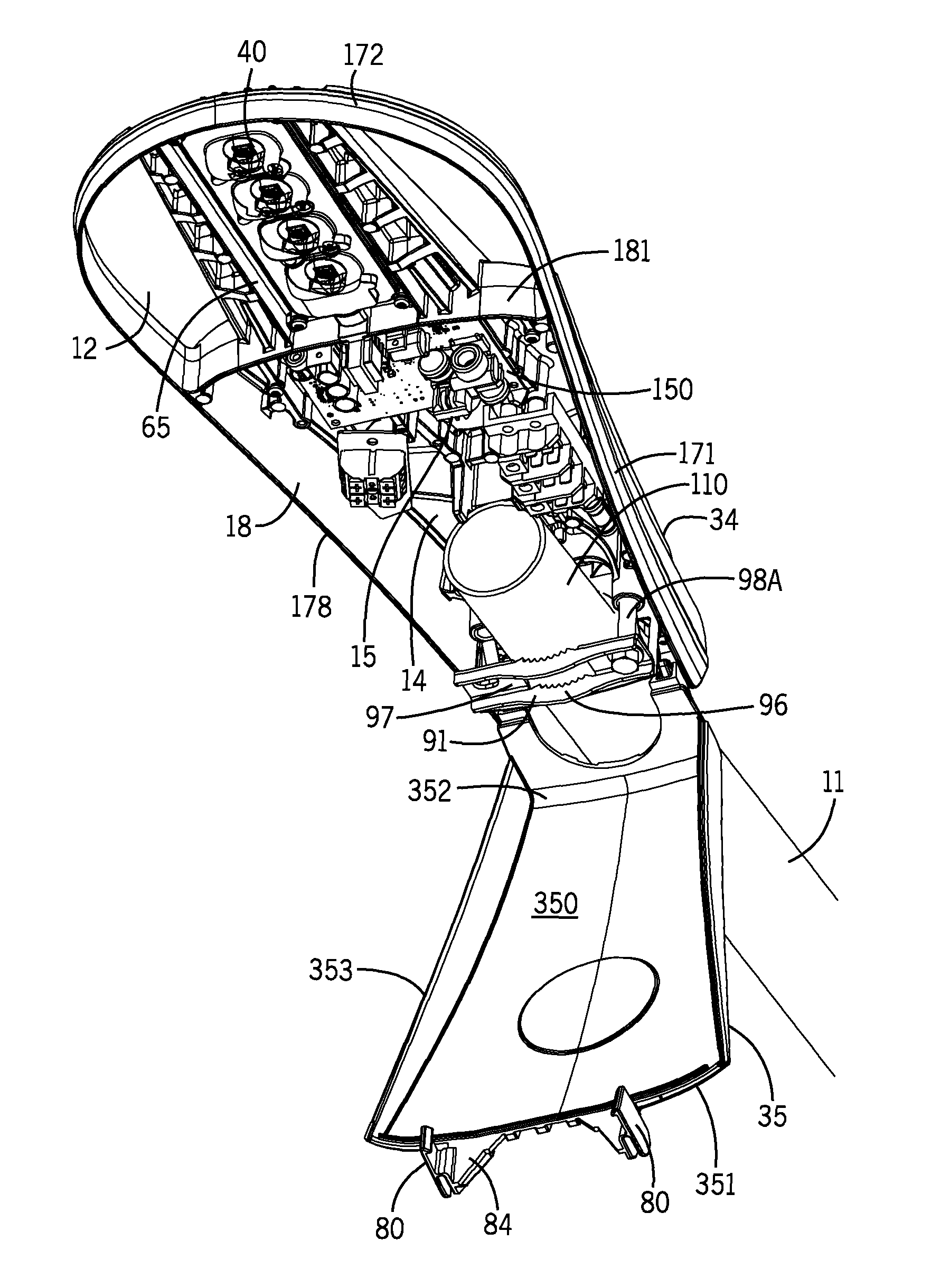
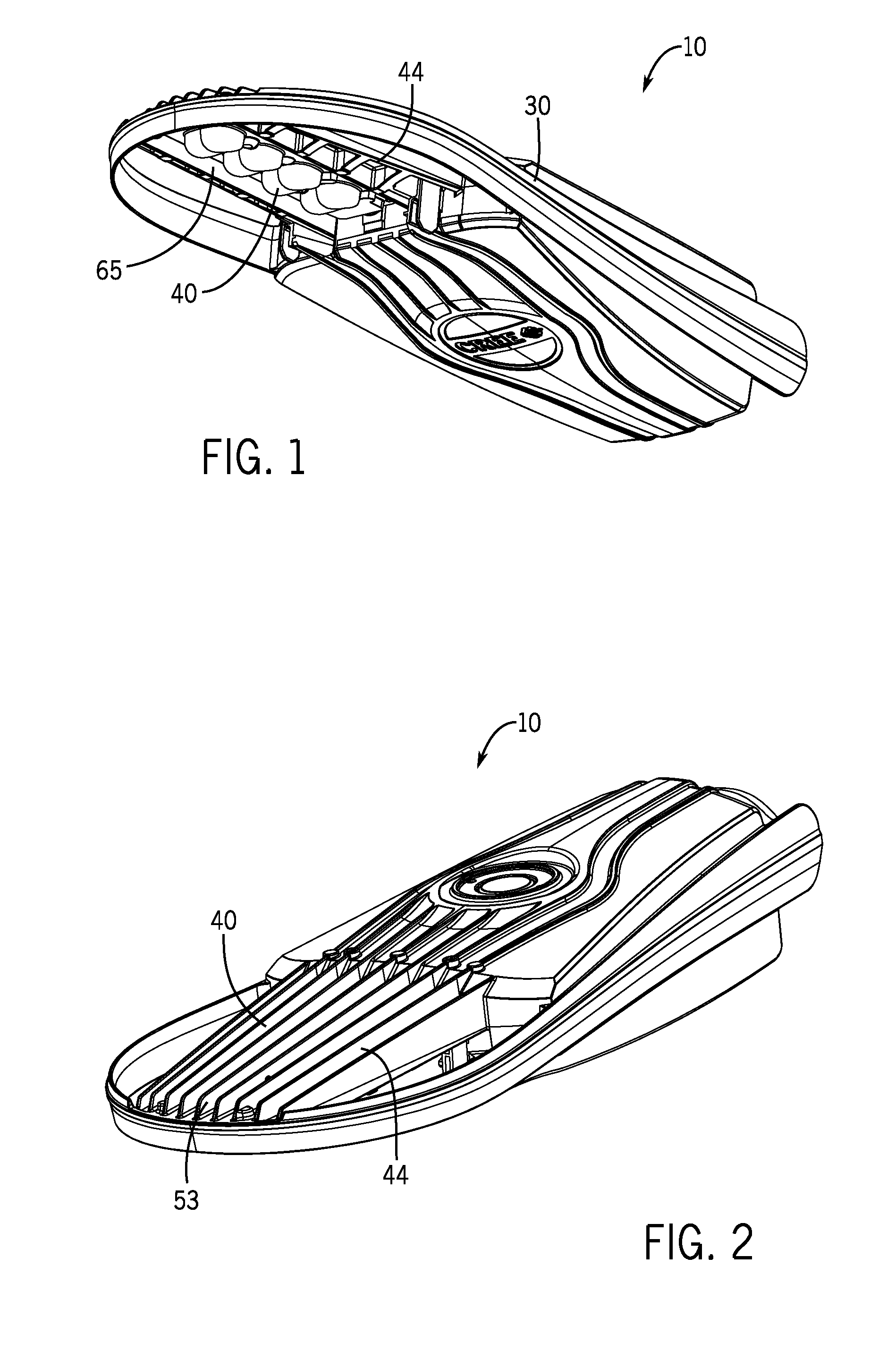
[0080]FIGS. 1-19, 32-33 and 35-37 illustrate a light fixture 10 which is a first embodiment in accordance with this invention. Light fixture 10 includes a frame 30 and an LED assembly 40 secured with respect to frame 30. Frame 30 surrounds and defines a forward open region 31 and a rearward region 32. Rearward region has a rearmost portion 33 adapted for securement to a support member 11. LED assembly 40 is positioned within open forward region 31 with open spaces 12 remaining therebetween—e.g., between either side of frame 30 and LED assembly 40. Other embodiments are possible where there are additional open spaces or one single open space.

[0081]LED assembly 40 includes a heat sink 42 and an LED illuminator 41 secured with respect to heat sink 42. Heat sink 42 includes an LED-supporting region 43 with heat-dissipating surfaces 44 extending from LED-supporting region 43. LED illuminator 41 is secured with respect to LED-supporting region 43. As shown in FIG. 5, LED illuminator 41 in...

third embodiment

[0097]Light fixture 10B of the third embodiment, shown in FIGS. 21 and 22 and which as indicated above includes frame 30B and heat sink 42B formed as a one-piece metal casting, has upper shell 34B and lower shell 35B both formed of polymeric material. The enclosure 13B which is formed by such polymeric shells is secured with respect to the metal casting of this embodiment.

[0098]A fourth embodiment of this invention is illustrated in FIGS. 23. In such embodiment, LED light fixture 10C has a non-metallic (polymeric) frame 30C. Frame 30C defines a forward open region 31C and has a rearward region 32C with a rearmost portion 33C adapted for securement to support member 11. FIGS. 24-26 illustrate a fifth embodiment of this invention. Light fixture 10D has an LED assembly 40D secured with respect to a non-metallic (polymeric) frame 30D. In the fourth and fifth embodiments, the frame itself serves to form the enclosure for the LED power circuitry, and such circuitry may include a fully-enc...

second embodiment

[0104]In the second embodiment illustrated in FIG. 20, fins 53A are configured such that between-fin channels 56A are open along the front and lateral sides of the heat sink

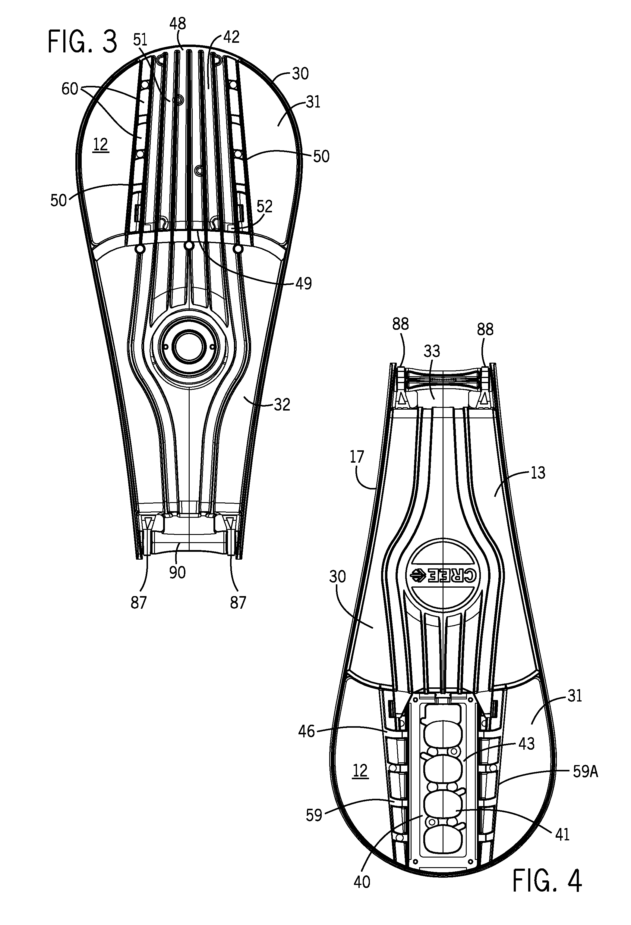
[0105]Referring again to the first embodiment, FIGS. 3 and 19 show rear fin-ends 55 configured to permit ambient-fluid flow from between-fin channels 56 to central-portion openings 52, thereby, facilitating liquid drainage therefrom. Liquid drainage from the top of heat sink 42 is facilitated by inclination of the top surface of heat sink 42, as explained more specifically below.

[0106]FIGS. 32 and 33 show between-fin surfaces 57 inclined off-horizontal when light fixture 10 is in its usual use orientation. More specifically, FIG. 32 shows surfaces 57 sloping toward lateral sides 50 of heat sink 42. FIG. 33 shows surfaces 57 sloping toward front and rear sides 48 and 49 of heat sink 42. In other words, portions of surfaces 57 are slightly but sufficiently downwardly inclined toward at least two dimensions and in t...


PUM


Abstract

An LED light fixture including a frame defining a forward open region and a rearward region with a rearmost portion adapted for securement to a support member. An LED assembly is secured with respect to the frame and positioned within the open forward region with open spaces remaining therebetween. The LED assembly includes an LED illuminator secured with respect to the LED-supporting region of a heat sink with an LED-supporting region and heat-dissipating surfaces extending therefrom. Another aspect of the invention is a non-metallic frame defining a forward open region and having a rearward region having a rearmost portion adapted for securement to a support member. An LED assembly is secured with respect to the frame and positioned within the open forward region with open spaces remaining therebetween.

Description

RELATED APPLICATION[0001]This application is a continuation-in-part of patent application Ser. No. 29 / 444,511, filed Jan. 31, 2013. The entirety of the contents of application Ser. No. 29 / 444,511 is incorporated herein by reference.FIELD OF THE INVENTION[0002]This invention relates to light fixtures and, more particularly, to light fixtures using light-emitting diodes (LEDs).BACKGROUND OF THE INVENTION[0003]In recent years, the use of light-emitting diodes (LEDs) in development of light fixtures for various common lighting purposes has increased, and this trend has accelerated as advances have been made in the field. Indeed, lighting applications which previously had typically been served by fixtures using what are known as high-intensity discharge (HID) lamps are now being served by LED light fixtures. Such lighting applications include, among a good many others, roadway lighting, factory lighting, parking lot lighting, and commercial building lighting.[0004]High-luminance light fi...

Claims


Application Information

Patent Timeline
Patent Type & Authority Patents(United States)
IPC IPC(8): F21S8/08F21V29/74F21V29/507F21V29/00F21V23/04H01L25/075H01L33/54F21V29/89F21V21/116F21W131/103F21W131/40F21Y101/02
CPCF21S8/086F21V29/507F21V29/74F21V21/116F21V23/045F21V29/89F21W2131/103H01L2924/0002F21W2131/40F21Y2101/02H01L25/0753H01L33/54H01L2924/00F21Y2115/10
Inventor KINNUNE, BRIANSNELL, NATHANSORENSON, JEREMY
Owner IDEAL IND LIGHTING LLC
Why Eureka
Try Eureka