
Transient air flow control

a technology of transient air flow and control, which is applied in the direction of electric control, combustion engines, machines/engines, etc., can solve the problems of poor torque response and/or transient egr disturbance, lag in desired airflow, and inability to maintain the desired cylinder egr amount, etc., to achieve rapid filling or unloading of the intake manifold, improve vehicle response and operator satisfaction, and reduce fuel economy

Active Publication Date: 2015-12-29
FORD GLOBAL TECH LLC
View PDF31 Cites 10 Cited by
  • Summary
  • Abstract
  • Description
  • Claims
  • Application Information

AI Technical Summary

Benefits of technology

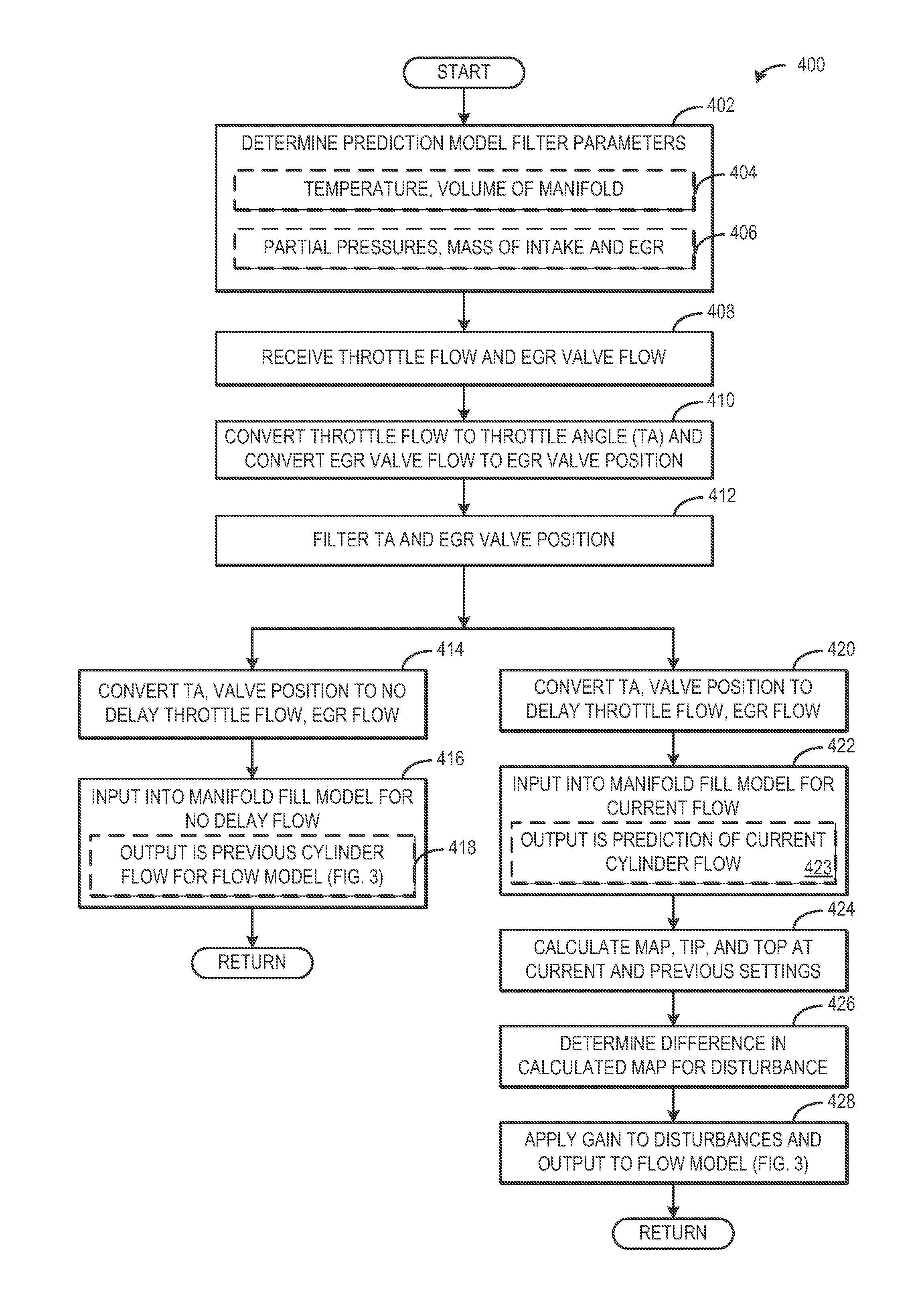
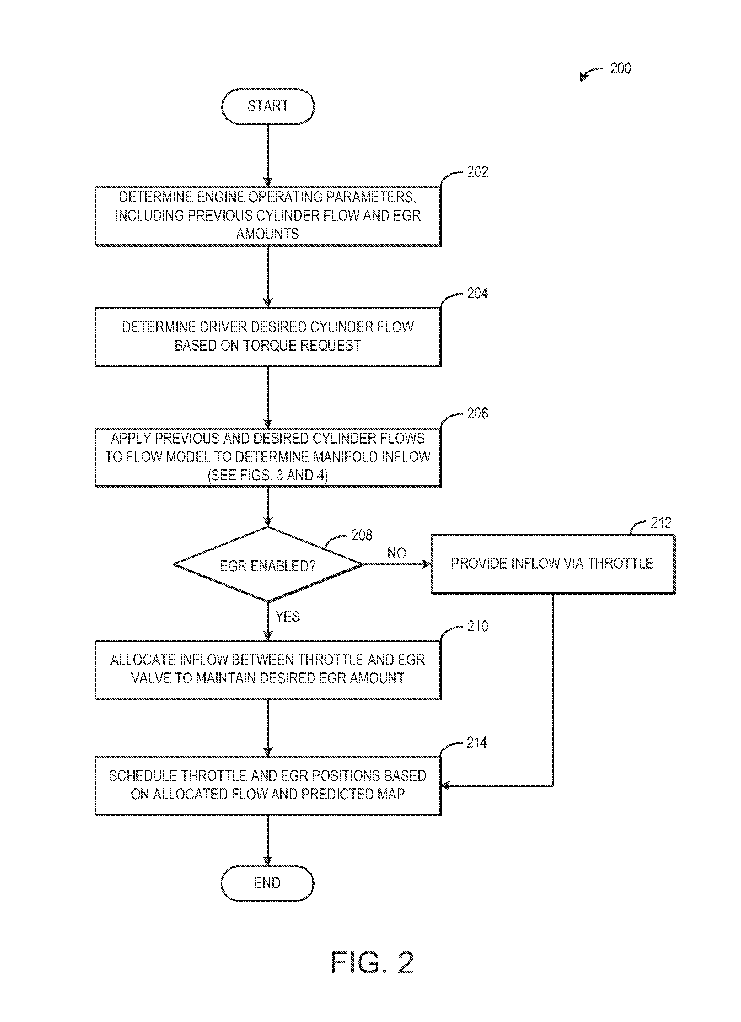
[0005]In this way, both the throttle and EGR valve may be controlled using transient airflow compensation to achieve rapid filling or unfilling of an intake manifold. Further, by allocating the flow between the throttle and the EGR valve, a desired EGR amount in the cylinder may be maintained. In one example, the desired cylinder airflow may be a prediction based on the previous cylinder airflow, a manifold filling model, and a driver torque request. The manifold filling model may determine a compensation airflow amount entering the manifold that rapidly drives the airflow leaving the manifold from the previous cylinder airflow amount to the desired cylinder airflow amount. This compensation airflow amount may be allocated between the throttle and the EGR valve to provide the desired cylinder airflow while maintaining a desired cylinder EGR amount.
[0006]The present disclosure may provide several advantages. First, transient conditions frequently result in torque fluctuations that can be unsatisfactory to a vehicle operator. By rapidly responding to a requested torque change, the present disclosure may improve vehicle response and operator satisfaction. Further, EGR disturbances during transient conditions may degrade combustion events, leading to reduced fuel economy and increased emissions. By maintaining desired EGR amounts even during transient events, fuel economy and emissions may be improved.

Problems solved by technology

However, during transient conditions, the intake manifold acts as an air buffer and thus the airflow reaching the cylinder may lead or lag desired airflow amounts entering into the manifold.
This may result in poor torque response and / or transient EGR disturbances.
While the disclosed models enable determination of EGR concentration during transient events, they do not provide for maintaining a desired cylinder EGR amount, nor do they overcome the delay often associated with achieving a desired cylinder airflow amount during a transient event.
First, transient conditions frequently result in torque fluctuations that can be unsatisfactory to a vehicle operator.
Further, EGR disturbances during transient conditions may degrade combustion events, leading to reduced fuel economy and increased emissions.

Method used


Image

  • Transient air flow control
  • Transient air flow control
  • Transient air flow control

Examples


Embodiment Construction

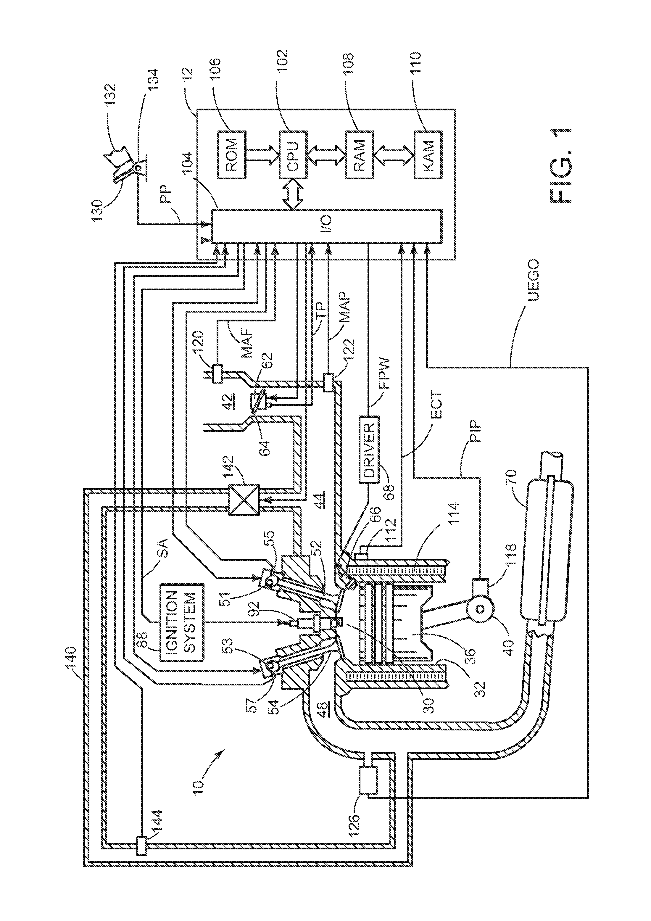
[0015]During a change in cylinder flow from an intake manifold, for example in response to a pedal tip-in event, airflow disturbances may result due to the delay associated with the filling or unfilling of the manifold. Thus, during transient conditions, delivered cylinder airflow may not match desired or commanded airflow. Closed-loop feedback control using sensors in the engine, such as manifold pressure and / or mass air flow sensors, may alleviate some of the issues in delivering desired cylinder flow during transient conditions, but sensor feedback is also associated with a response delay.

[0016]By using a manifold filling model that predicts a change in a cylinder flow amount based on a previous cylinder flow amount and a constant volumetric efficiency state of the manifold, accurate determination of desired cylinder flow may be provided without reliance on sensors. Further, because the model may predict a manifold inflow amount that drives the previous cylinder flow to the desir...


PUM


Abstract

Embodiments for controlling cylinder air flow are provided. In one example, a method for controlling airflow into a cylinder of an engine comprises, if a previous cylinder airflow is different than a desired cylinder airflow, allocating flow into an intake manifold between a throttle and an EGR valve to provide the desired cylinder airflow while maintaining a desired EGR amount in the cylinder. In this way, transient air flow requests may be met without delay while maintaining desired cylinder EGR amounts.

Description

FIELD[0001]The present disclosure relates to controlling airflow into a cylinder.BACKGROUND AND SUMMARY[0002]During steady state conditions, airflow into an intake manifold of an engine via a throttle and EGR may be allocated to deliver a desired cylinder airflow amount while maintaining desired EGR in the cylinder. However, during transient conditions, the intake manifold acts as an air buffer and thus the airflow reaching the cylinder may lead or lag desired airflow amounts entering into the manifold. This may result in poor torque response and / or transient EGR disturbances.[0003]U.S. Pat. No. 5,273,019 describes a model for predicting mass air flow into an engine, both with and without EGR, during the same transient condition event. Based on a difference between the models, the percentage of the mass flow that derives from EGR may be determined. While the disclosed models enable determination of EGR concentration during transient events, they do not provide for maintaining a desi...

Claims


Application Information

Patent Timeline
Patent Type & Authority Patents(United States)
IPC IPC(8): F02D41/00F02D21/08F02D9/02F02D41/14
CPCF02D41/0002F02D21/08F02D41/0052F02D41/0072F02D2009/0276F02D2041/0017Y02T10/47F02D2041/1431F02D2200/0402F02D2250/28F02D2250/36Y02T10/42F02D2041/1412Y02T10/40
Inventor ROLLINGER, JOHN ERICGATES, FREEMAN CARTERFULTON, BRIEN LLOYDRACELIS, ROMMEL
Owner FORD GLOBAL TECH LLC
Learn More