
Assembly for dispensing a canister's liquid contents into a vessel and for rinsing a residue of the liquid contents

a technology for dispensing canisters and liquid contents, which is applied in the direction of transportation and packaging, hollow article cleaning, packaging, etc., can solve the problems of affecting the downward flow of the rinsed liquid, impede the downward emission and dispensing of fluid into the tank, etc., and achieves enhanced canister rinsing, efficient rinsing of walls and floors, and enhanced chemical dispensing

Active Publication Date: 2015-12-22
ECK ETHAN
View PDF12 Cites 3 Cited by
  • Summary
  • Abstract
  • Description
  • Claims
  • Application Information

AI Technical Summary

Benefits of technology

The patent describes an assembly for cleaning containers such as canisters. The assembly includes a lance with a rinsing mechanism for cleaning residues from the container. The rinsing mechanism is connected to the lance and emits water in the form of jets to flush out the residues from the interior of the container. The rinsing mechanism is positioned to enhance the rinsing effect during the downward thrust of the container over the lance. The assembly also includes a mandrel that is designed to improve the dispensing of chemicals from the container. The mandrel is configured to deflect the floor's leaf sections and speed up the purging of fluid into the container. The from of the rinsing mechanism and the use of the mandrel in the assembly make it more efficient in cleaning the container and dispensing chemicals.

Problems solved by technology

Such assemblies often allow incised edges of the canister's floor to directly abut or impinge against side surfaces of cutting blades, and such edge contacts often undesirably impede the downward emission and dispensation of the fluid into the tank.
Such impingements of incised floor edges against cutting blade surfaces also undesirably tend to resist and interfere with subsequent upward and inward flows of residue rinsing water, and further interfere with downward flows of the rinsed residual herbicide, pesticide, or fertilizer.

Method used


Image

  • Assembly for dispensing a canister's liquid contents into a vessel and for rinsing a residue of the liquid contents
  • Assembly for dispensing a canister's liquid contents into a vessel and for rinsing a residue of the liquid contents
  • Assembly for dispensing a canister's liquid contents into a vessel and for rinsing a residue of the liquid contents

Examples


Embodiment Construction

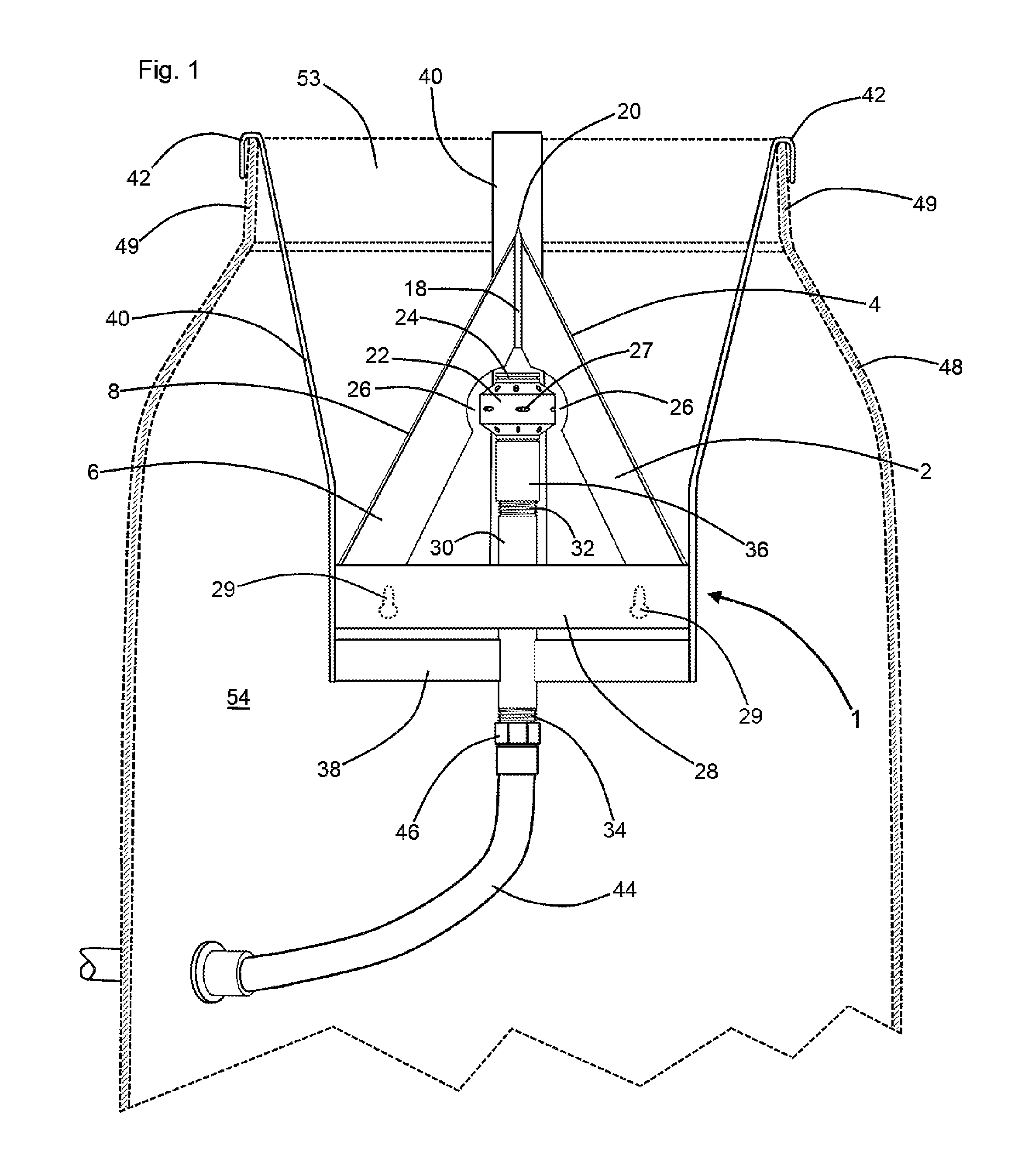
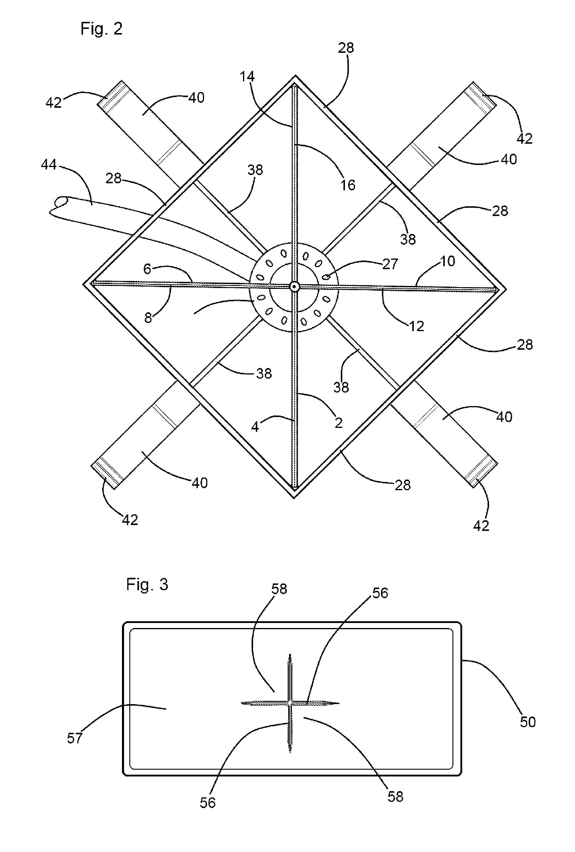
[0021]Referring now to the drawings and in particular simultaneously to FIGS. 1 and 2, an “A” lance component of the instant inventive assembly is referred to generally by Reference Arrow 1. Like the structure of a common capital letter “A”, the instant invention's “A” lance 1 preferably has a plurality of legs 2, 6, 10 and 14. The “A” lance's legs 2, 6, 10, and 14 are configured as blades which respectively have outer sharpened edges 4, 8, 12, and 16. The upper ends of the “A” lance's legs 2, 6, 10, and 14 are preferably fixedly welded to a steel bar stock member 18, and such legs 4, 6, 10, and 14 in combination with the upper end of bar stock 18, form a canister floor piercing point 20.

[0022]Referring further simultaneously to FIGS. 1 and 2, the instant invention's “AA” lance further includes a bar member 22,26 which spans laterally between legs 2, 6, 10, and 14, the bar member 22,26 corresponding with the horizontally extending cross bar component of a common capital letter “A”. ...


PUM


Abstract

An assembly for purging a canister into a tank and for rinsing the canister, the canister having a floor, the assembly including a “A” configured lance having a plurality of legs and a bar, each leg among the plurality of legs forming a blade having an upper end and an outer edge, the blades' upper ends and outer edges being sharpened for, upon upward impingement against the canisters' floor, dividing the floor into a plurality of sections, each section among the plurality of sections being configured as a flexible leaf, the bar member forming and functioning both as a leaf deflecting mandrel, and as a rotatable sprinkler head, the “A” configured lance and associated sprinkler head configured mandrel being mountable within the tank by suspension hooks.

Description

CLAIM OF PRIORITY FROM PREVIOUSLY FILED PROVISIONAL PATENT APPLICATION[0001]This non-provisional patent application claims the benefit of and priority from U.S. Provisional Patent Application No. 61 / 725,134 filed Nov. 12, 2012, and entitled “Method and Apparatus for Chemical Media Transfer”. The inventor and applicant named in said U.S. Provisional Patent Application No. 61 / 725,134 is one and same person as the inventor and applicant in the instant application. Structures and functions of structures disclosed and described in the instant application are substantially identical to those disclosed in said provisional application.FIELD OF THE INVENTION[0002]This invention relates to apparatus and assemblies which are adapted for transferring the liquid contents of herbicide, pesticide, or fertilizer canisters and bottles into larger vessels such as tanks of agricultural sprayers, and which are adapted for subsequently rinsing such canisters and bottles. More particularly, this inventio...

Claims


Application Information

Patent Timeline
Patent Type & Authority Patents(United States)
IPC IPC(8): B08B9/093B67D3/00B08B9/08A01M7/00
CPCB67D3/0061B08B9/093B08B9/0826A01M7/0085
Inventor ECK, ETHAN
Owner ECK ETHAN
Learn More