Photo-alignment exposure device and photo-alignment exposure method

a technology of alignment exposure and exposure method, which is applied in the direction of microlithography exposure apparatus, photomechanical treatment, instruments, etc., can solve the problem of width that cannot be ignored, and achieve the effect of sufficient effective image area to narrow the unit image area

Active Publication Date: 2015-12-08
V TECH CO LTD
View PDF8 Cites 0 Cited by
  • Summary
  • Abstract
  • Description
  • Claims
  • Application Information

AI Technical Summary

Benefits of technology

[0012]Thus, one or more embodiments of the invention eliminate the alignment disorder near the boundary of the divided areas, which are obtained by dividing a unit image area, and ensuring an effective image area sufficient to narrow the unit image area when the photo-alignment exposure system is used in the multi-domain method.
[0017]With the photo-alignment exposure device and photo-alignment exposure method, the alignment disorder near the boundary of the divided areas obtained by dividing a unit image area can be eliminated and an effective image area sufficient to narrow the unit image area can be ensured when the photo-alignment exposure system is used in the multi-domain method.

Problems solved by technology

However, a transition to high-definition liquid crystal display panels created a demand for a smaller width of the unit image area Pa, and where a sufficient effective image area is to be ensured, such a width cannot be ignored.

Method used


Image

  • Photo-alignment exposure device and photo-alignment exposure method
  • Photo-alignment exposure device and photo-alignment exposure method
  • Photo-alignment exposure device and photo-alignment exposure method

Examples


Embodiment Construction

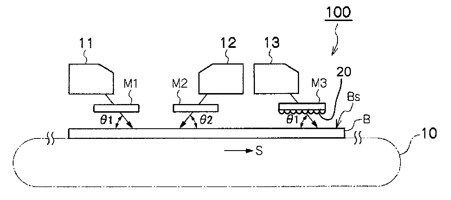
[0023]The embodiments of the invention will be explained hereinbelow with reference to the drawings. FIG. 3 is an explanatory drawing illustrating the photo-alignment exposure device and photo-alignment exposure method according to an embodiment of the present invention. FIG. 3(a) depicts a configuration example of the photo-alignment exposure device and FIG. 3(b) depicts an example of an exposed base plate (exposed surface).

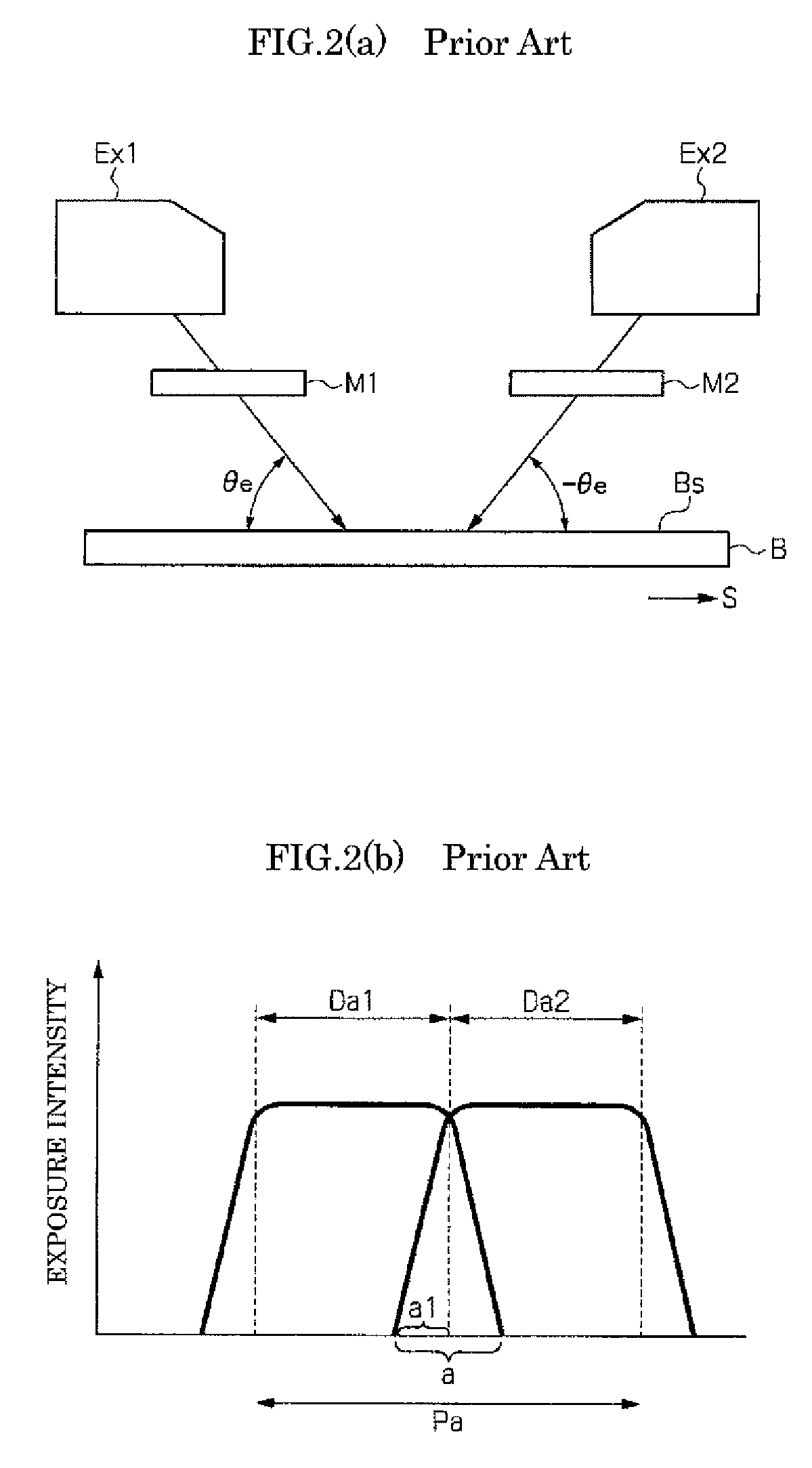
[0024]As depicted in FIG. 3(b), a photo-alignment exposure device 100 is a device that divides each unit image area Pa of a liquid crystal display into a plurality of divided areas Da1, Da2, and photo-aligning an alignment material film of the respective divided areas Da1, Da2 in mutually different directions. The alignment material film referred to herein is a photosensitive polymeric membrane demonstrating a reversible photoisomerization reaction, and the alignment with the desired pre-tilt angle and in the direction along the radiation direction is obtained i...


PUM

PropertyMeasurementUnit
irradiation angleaaaaaaaaaa
widthaaaaaaaaaa

Abstract

A photo-alignment exposure device that includes a first mask and a first exposure device that independently proximity-exposes a first divided area, a second mask and a second exposure device that independently proximity-exposes a second divided area adjacent to the first divided area, and a third mask and a third exposure device that exposes an area on a side of the first divided area near a boundary between the first divided area and the second divided area. The third exposure device is provided with a photo-irradiation angle same as that of the first exposure device or the second exposure device with respect to an exposed surface. A condensing element that condenses the mask transmitted light on the area on a side of the first divided area near the boundary is provided between the mask opening of the third mask and the exposed surface.

Description

TECHNICAL FIELD[0001]Embodiments of the invention relate to a photo-alignment exposure device and a photo-alignment exposure method that forms an alignment film of a liquid crystal display.RELATED ART[0002]A photo-alignment exposure system is known, in which a photosensitive polymeric membrane that is to serve as an alignment film is obliquely irradiated with an ultraviolet ray in order to define the size of the pre-tilt angle and alignment direction of liquid crystal, as a system that forms an alignment film of a liquid crystal display.[0003]Meanwhile, the viewing angle of a liquid crystal panel is modified by dividing a single unit image area (a pixel or a sub-pixel, or an aggregation area thereof) of a liquid crystal display into two or more areas and changing the alignment direction of the liquid crystal for each divided area, and this method is called a pixel division method or a multi-domain method.[0004]When the aforementioned photo-alignment exposure system is used in the mu...

Claims


Application Information

Patent Timeline
Patent Type & Authority Patents(United States)
IPC IPC(8): G02F1/1337G03F7/20G02F1/13
CPCG02F1/133788G02F1/1303G02F1/133753G03F7/201G03F7/70275G03F7/70283G03F7/70308G03F7/70325G03F7/70358G02F2001/133757G02F1/133757G03F7/20
Inventor KAJIYAMA, KOICHIHASHIMOTO, KAZUSHIGEARAI, TOSHINARI
Owner V TECH CO LTD
Why Eureka
Try Eureka