Balancer

a technology of balancer and balancer plate, which is applied in the field of balancer, can solve the problems of inability to adapt to the rotational conditions of changes, and create dynamic imbalances, and achieve the effects of effective correction of dynamic imbalance, and remarkable extension of the service life of the grinding wheel

Active Publication Date: 2015-12-08
YAMAMOTO HIROAKI
View PDF26 Cites 4 Cited by
  • Summary
  • Abstract
  • Description
  • Claims
  • Application Information

AI Technical Summary

Benefits of technology

[0026]According to the balancer of the present invention, by making the receiving surface of the storage chamber concave curved and the second and third pressing surfaces of the weight convex curved, or, in the alternative, by making the storage chamber and the weight entirely cylindrical, it is possible to effectively correct dynamic imbalance, not only in the direction of the X-Z plane, but also in the direction of the Z-axis (rotation axis), in instances where there is change in rotation conditions, that is, when there is change in rotation speed or in the amount of rotation of the rotatable body.
[0027]Due to the above, the balancer of the present invention enables effective correction of dynamic imbalance, not only when the rotatable body rotates at high speed, but also when it rotates at low speed. As such, it is possible to obtain a balancer adaptable to both high and low speeds of a rotatable body, that is, a balancer adaptable to any rotation speed thereof. Also, dynamic imbalance is corrected in all directions of X, Y, and Z which create a three-dimensional space. Therefore, when the balancer of the present invention is applied to a rotatable body, being, for example, a grinding / abrading machine comprising a grinding wheel, the service life of the grinding wheel is remarkably extended since the grinding wheel wears away in a uniform manner and not in a non-uniform manner. Likewise, when the balancer is applied to spindles for various machine tools, the respective wear limits of the spindles are extended. Also, the highly accurate and simple mechanical structure of the balancer makes electricity, oil, and air pressure unnecessary, and the design and production thereof which depend on the shape of the main shaft of the machines, enables the main shaft to be in any shape.
[0028]Also, when the balancer of the present invention is applied to a grinding / abrading machine comprising a grinding wheel and the machine is used to grind a target material to create recesses therein, the resultant recesses are able to have a mirror-like finish due to improvement in grinding precision, unquestionably at the recess bottom, and particularly at the recess side walls where grinding has been insufficient until now.
[0029]Also, in instances where the weight of the balancer has a single structure, when the rotatable body is with a designated resonant frequency and thus rotates at that resonant frequency, the balancer slightly deteriorates in its ability to correct dynamic imbalance. However, by configuring the weight to have a double structure comprising an outer weight and an inner weight, it is possible to remarkably reduce deterioration of the balancer in its ability to correct dynamic imbalance due to such resonant frequency.
[0030]Furthermore, with respect to the balancer of the present invention, the weight has a shape similar to and smaller than the shape of the storage chamber; the storage chamber is a cylindrical space extending alongside a central axis of the storage chamber and has end surfaces perpendicular to the central axis, the end surfaces both being concave curved; respective midpoints of the respective central axes of the storage chambers are contact points on a circumference of a circle having the rotation axis as its center, the circle being on an arbitrary plane perpendicular to the rotation axis; and the midpoints are positioned in a manner such that they create a rotational symmetry around the rotation axis. By the above, processing is made easier than in prior art. Therefore, production costs can be kept low, without there being any deterioration of the balancer in its ability to correct dynamic imbalance.

Problems solved by technology

Therefore, although balance immediately after correction would be fine, dynamic imbalance would be created again in instances where there is remarkable change in rotation speed or change in the weight of the rotatable body due to tool changing or the like, since there would also be change in the balance corrective value.
That is, adaptation to changes in rotation conditions has not been possible, thus requiring balance correction every time there is change in rotation conditions.

Method used


Image

  • Balancer
  • Balancer
  • Balancer

Examples


first embodiment

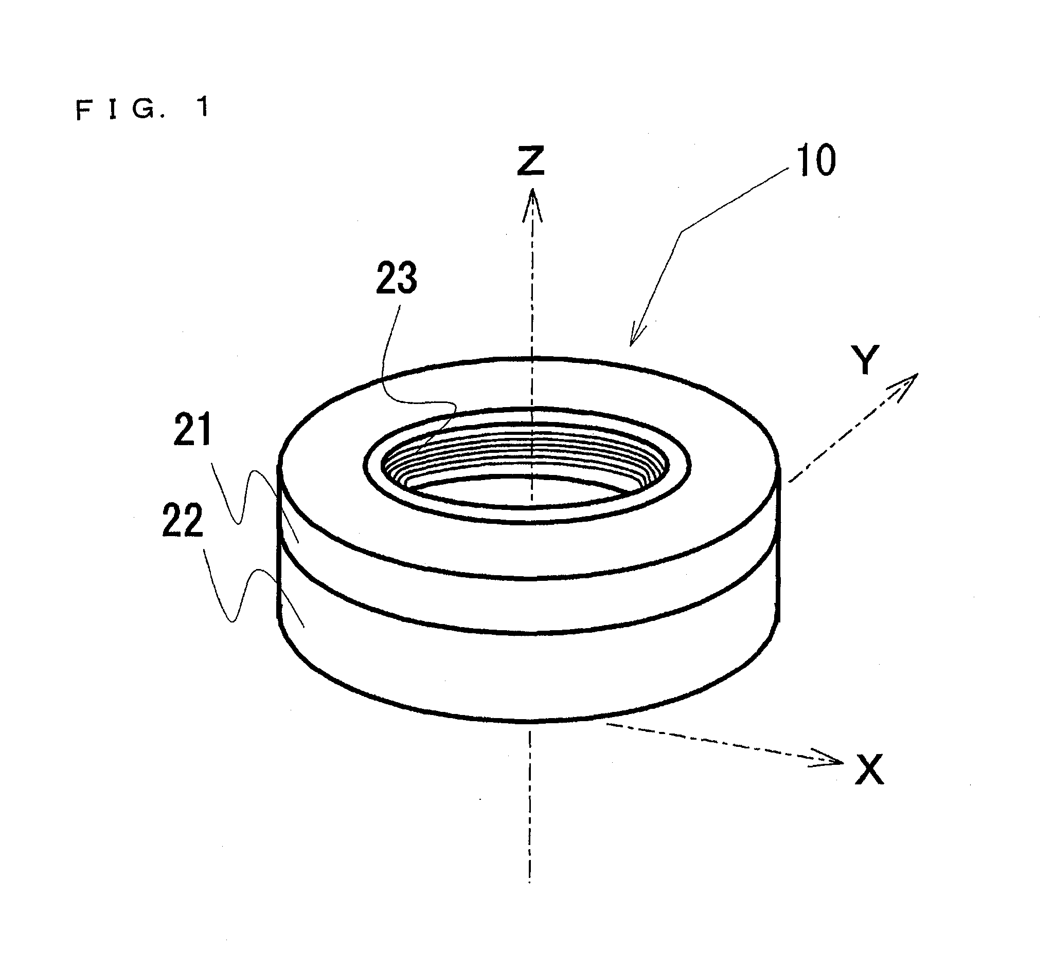
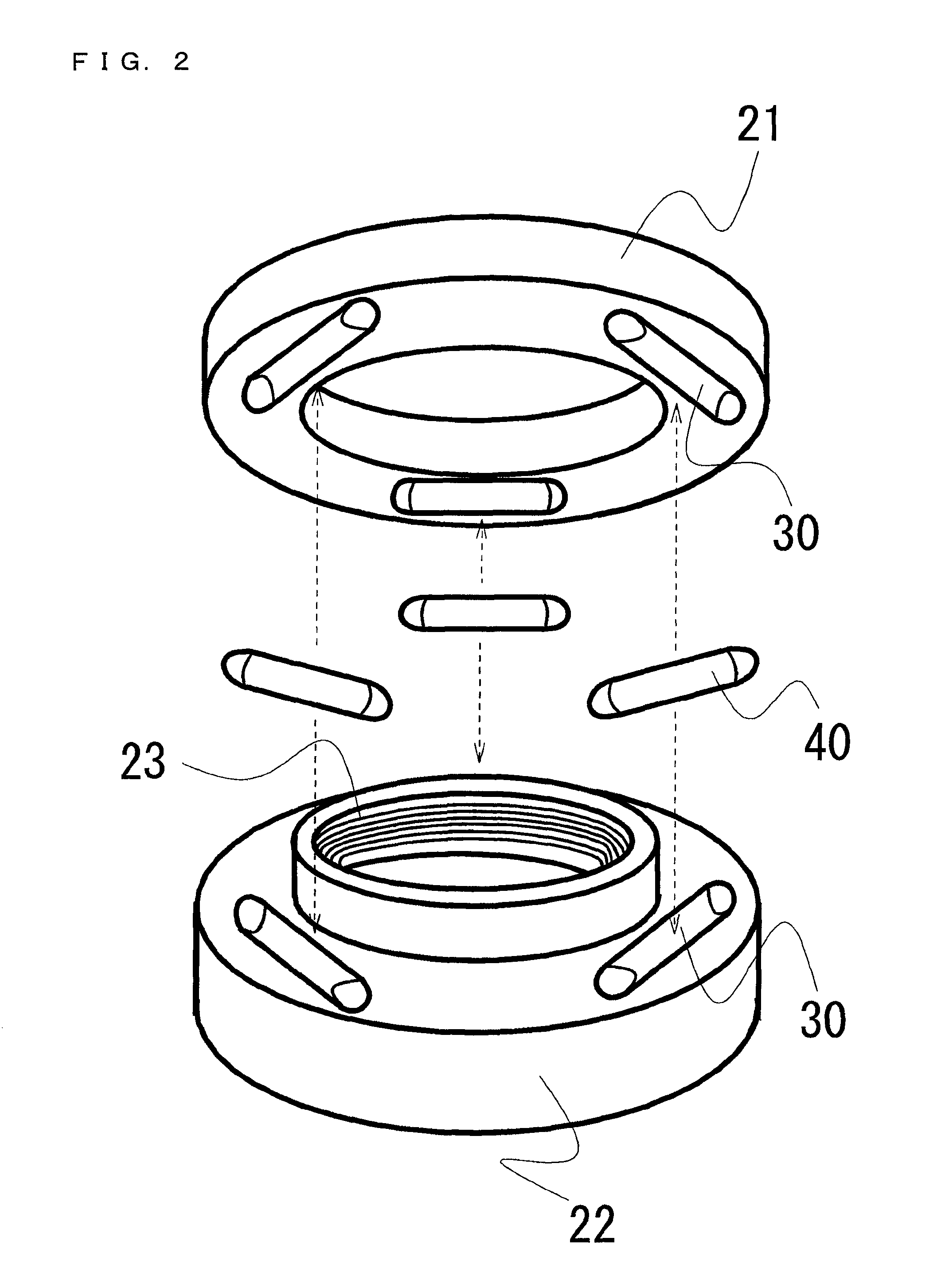
[0048]FIG. 2 is an exploded view of a first embodiment of the balancer of the present invention. The weight 40 used in the first embodiment has a cylindrical shape, its end portions being curved as will be described later. Therefore, in terms of processing, it is easy for the storage chambers 30 to be disposed as illustrated in FIG. 2. That is, the balancer is divided at its center into the weight holder cover 21 and the weight holder body 22, and then, the storage chambers 30 are provided therein by drilling.

[0049]The storage chamber 30 in the first embodiment of the balancer 10 is a cylindrical space, and therefore has a central axis. Respective surfaces of the ends of this cylinder, that is, end surfaces of this cylinder both perpendicular to the central axis, are curved and not flat.

[0050]Also, the weight 40 in the first embodiment of the balancer 10 has a cylindrical shape as illustrated in FIG. 4, and both of end surfaces 41 of this cylinder are curved. That is, the weight 40 ...

second embodiment

[0054]FIG. 6 is an exploded view of a second embodiment of the balancer 10 of the present invention. The weight 40 used in the second embodiment is housed in the storage chamber 30 which is inclined away from the rotation axis (Z-axis), as will be described later. Therefore, in terms of processing, it is not easy for the storage chambers 30 to be disposed in the manner as illustrated in FIG. 2, which is by dividing the balancer at its center into the weight holder cover 21 and the weight holder body 22 and then providing the storage chambers therein by drilling. Therefore, it would be convenient if the storage chamber 30 is drilled in either one of the weight holder cover 21 and the weight holder body 22 (in the case of FIG. 6, this applies to the weight holder body), and the abutting surface of the other (in the case of FIG. 6, this applies to the weight holder cover) serves as a cover for weight insertion openings 37 of the storage chambers 30.

[0055]The storage chamber 30 in the s...

third embodiment

[0062]The third embodiment of the balancer 10 of the present invention is the same as the second embodiment, with the exception that the weight 40 comprises: an inner weight 60; and an outer weight 50 having a pocket drilled therein, the pocket capable of having the inner weight 60 inserted therein. Specifically, the third embodiment is as illustrated in FIG. 10. In FIG. 10, the shape of the weight in the third embodiment of the balancer 10 is represented by a six-view orthographic projection. The rear view and the left side view appear the same as the front view (A) and the right side view (B), respectively, and are thus omitted. Note that (C) is the top view, and (D) is the bottom view.

[0063]With respect to the weight 40 in the third embodiment, the outer weight 50 results from drilling an inner-weight-insertion opening at a position corresponding to that of the third pressing surface 45 of the weight 40 in the second embodiment; and allowing the opening to extend toward the secon...


PUM


Abstract

[Problem to be Solved]To provide a balancer that can correct dynamic imbalance in rotatable bodies such as machine tools. The correction for low-speed rotation is possible to the same extent as that for high-speed rotation.[Solution to Problem]The balancer, attachable via its attaching portion to a rotatable body, and rotatable together therewith about its rotation axis, includes: weights of same mass and shape; and a weight holder with storage chambers for housing the weights, respectively, such that the weights can oscillate in arbitrary directions. The weight is shaped similar to and smaller than the chamber. The chamber is a cylindrical space extending alongside its central axis; and has concave curved ends perpendicular to the central axis. Midpoints of the central axes of the chambers are contact points on a circumference of a circle having the rotation axis as its center and being on an arbitrary plane perpendicular to the rotation axis; and are positioned so that they create a rotational symmetry around the rotation axis.

Description

TECHNICAL FIELD[0001]The present invention relates to a balancer for suppressing vibration caused during rotation in various rotatable bodies such as various machine tools.BACKGROUND ART[0002]With respect to rotatable bodies such as various machine tools, it is necessary to correct dynamic imbalance caused by vibration, etc. at times of rotation. Until now, dynamic imbalance has been corrected by measuring and obtaining the amount and phase angle of imbalance, with use of a balance measuring device; and then shedding off or adding the amount equivalent to the amount of the imbalance. However, correction of such dynamic imbalance has been a fixed balance correction made for a certain rotation speed designated for measurement. Therefore, although balance immediately after correction would be fine, dynamic imbalance would be created again in instances where there is remarkable change in rotation speed or change in the weight of the rotatable body due to tool changing or the like, since...

Claims


Application Information

Patent Timeline
Patent Type & Authority Patents(United States)
IPC IPC(8): F16F15/14F16F15/16F16F15/36B23B5/22B24B41/00F16C15/00
CPCF16F15/36Y10T74/2128
Inventor YAMAMOTO, HIROAKI
Owner YAMAMOTO HIROAKI
Why Eureka
Try Eureka