Balancer
a technology of balancer and balancer plate, applied in the direction of spring/damper, rotating vibration suppression, vibration suppression adjustment, etc., can solve the problems of inability to adapt to the change in rotation conditions, dynamic imbalance would be created, etc., to achieve effective dynamic imbalance correction, and remarkable service life of the grinding wheel
- Summary
- Abstract
- Description
- Claims
- Application Information
AI Technical Summary
Benefits of technology
Problems solved by technology
Method used
Image
Examples
first embodiment
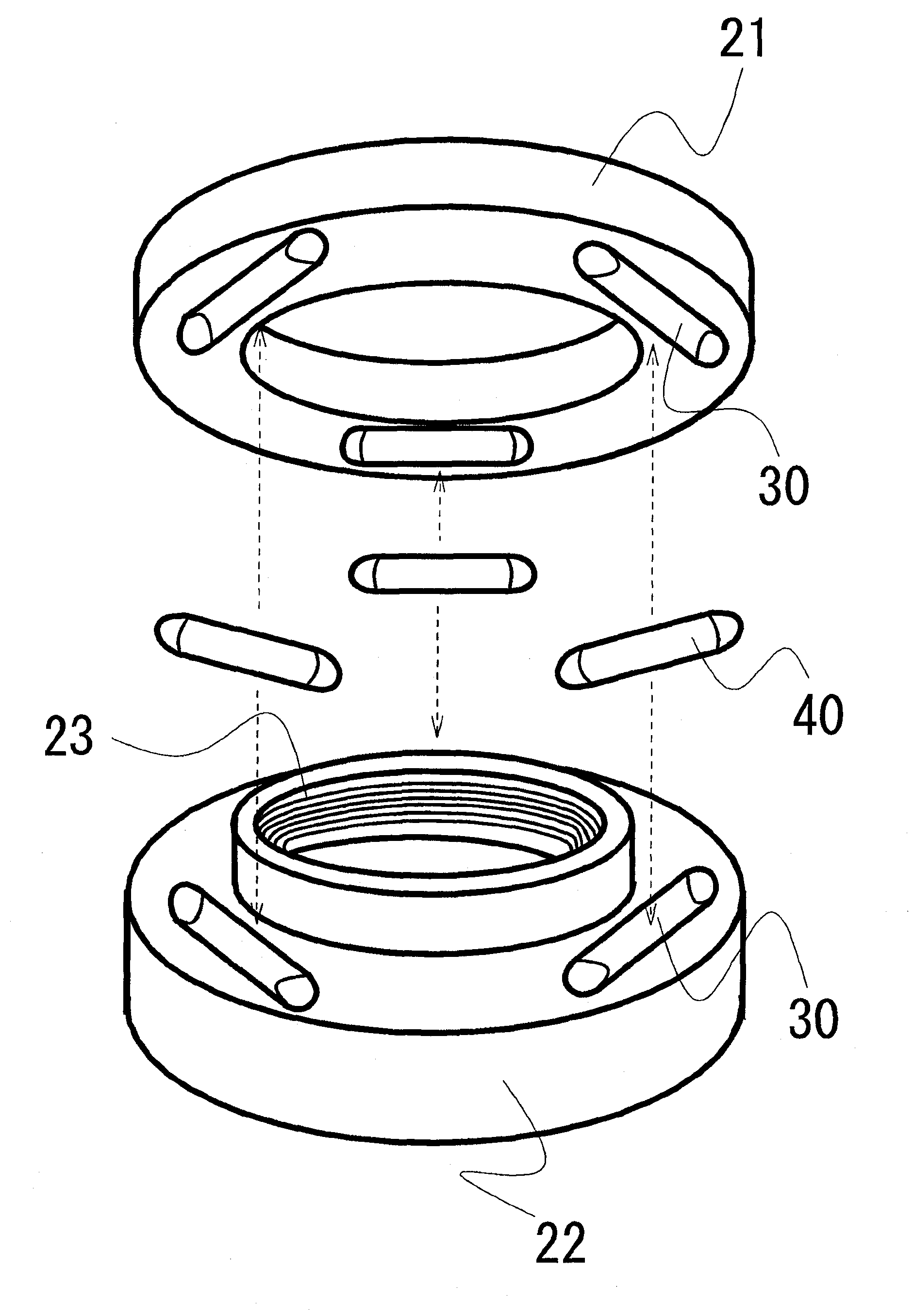
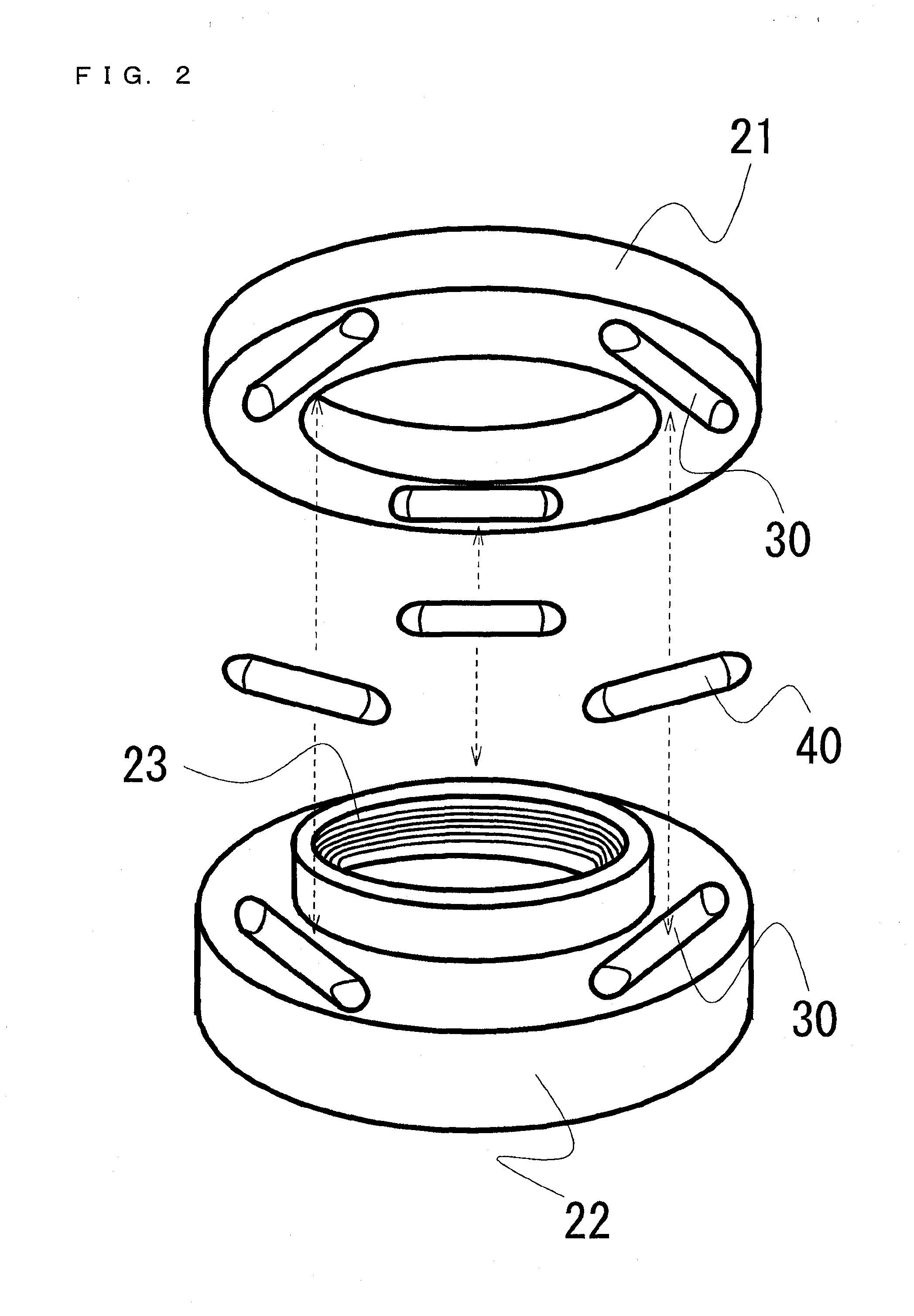
[0048]FIG. 2 is an exploded view of a first embodiment of the balancer of the present invention. The weight 40 used in the first embodiment has a cylindrical shape, its end portions being curved as will be described later. Therefore, in terms of processing, it is easy for the storage chambers 30 to be disposed as illustrated in FIG. 2. That is, the balancer is divided at its center into the weight holder cover 21 and the weight holder body 22, and then, the storage chambers 30 are provided therein by drilling.
[0049]The storage chamber 30 in the first embodiment of the balancer 10 is a cylindrical space, and therefore has a central axis. Respective surfaces of the ends of this cylinder, that is, end surfaces of this cylinder both perpendicular to the central axis, are curved and not flat.
[0050]Also, the weight 40 in the first embodiment of the balancer 10 has a cylindrical shape as illustrated in FIG. 4, and both of end surfaces 41 of this cylinder are curved. That is, the weight 40 ...
second embodiment
[0054]FIG. 6 is an exploded view of a second embodiment of the balancer 10 of the present invention. The weight 40 used in the second embodiment is housed in the storage chamber 30 which is inclined away from the rotation axis (Z-axis), as will be described later. Therefore, in terms of processing, it is not easy for the storage chambers 30 to be disposed in the manner as illustrated in FIG. 2, which is by dividing the balancer at its center into the weight holder cover 21 and the weight holder body 22 and then providing the storage chambers therein by drilling. Therefore, it would be convenient if the storage chamber 30 is drilled in either one of the weight holder cover 21 and the weight holder body 22 (in the case of FIG. 6, this applies to the weight holder body), and the abutting surface of the other (in the case of FIG. 6, this applies to the weight holder cover) serves as a cover for weight insertion openings 37 of the storage chambers 30.
[0055]The storage chamber 30 in the s...
third embodiment
[0062]The third embodiment of the balancer 10 of the present invention is the same as the second embodiment, with the exception that the weight 40 comprises: an inner weight 60; and an outer weight 50 having a pocket drilled therein, the pocket capable of having the inner weight 60 inserted therein. Specifically, the third embodiment is as illustrated in FIG. 10. In FIG. 10, the shape of the weight in the third embodiment of the balancer 10 is represented by a six-view orthographic projection. The rear view and the left side view appear the same as the front view (A) and the right side view (B), respectively, and are thus omitted. Note that (C) is the top view, and (D) is the bottom view.
[0063]With respect to the weight 40 in the third embodiment, the outer weight 50 results from drilling an inner-weight-insertion opening at a position corresponding to that of the third pressing surface 45 of the weight 40 in the second embodiment; and allowing the opening to extend toward the secon...
PUM
 Abstract
Description
Claims
Application Information
 - R&D
- Intellectual Property
- Life Sciences
- Materials
- Tech Scout
- Unparalleled Data Quality
- Higher Quality Content
- 60% Fewer Hallucinations
Browse by: Latest US Patents, China's latest patents, Technical Efficacy Thesaurus, Application Domain, Technology Topic, Popular Technical Reports.
© 2025 PatSnap. All rights reserved.Legal|Privacy policy|Modern Slavery Act Transparency Statement|Sitemap|About US| Contact US: help@patsnap.com


