Coil system and housing

a coil system and coil technology, applied in the direction of transformers/inductance coils/windings/connections, inductances, electrical devices, etc., can solve the problems of coils not properly transferring current, current use of combustion management systems, and risk of unwanted arcing

Active Publication Date: 2015-12-01
PROFIRE ENERGY
View PDF5 Cites 2 Cited by
  • Summary
  • Abstract
  • Description
  • Claims
  • Application Information

AI Technical Summary

Benefits of technology

[0016]According to one aspect of the invention, a coil housing is provided that protects the coil and coil terminals from external elements and unwanted contacts. The coil housing may restrict coil and terminal contact with external elements and thereby reduces the risk of unwanted arcing.
[0028]The previously described aspects of the invention have many advantages, including reducing unwanted arcing during coil maintenance, allowing more convenient placement of the coil, providing easier access for maintenance, facilitating the use of a fourth terminal, providing for flame and / or spark detection, and protecting the transformer coil and coil terminals from external agents that might cause unwanted arcing.

Problems solved by technology

However, coil housings currently used in combustion management systems have a number of disadvantages.
One disadvantage with coil housings currently being used in combustion management systems at oil and gas well sites is the risk of unwanted arcing, particularly between terminals, because of the high voltage generated by the coils.
When unwanted arcing occurs, the coil may not transfer current properly.
Further, unwanted arcing increases the risk of damage or injury to equipment and personnel.
The risk of unwanted arcing may increase when terminals have more exposure to air.
The risk of unwanted arcing may also increase as the distance between the terminals decreases.
Coil systems currently being used in connection with combustion management systems may have several terminals which extend outside the coil housing, thus being significantly exposed to air.
Another disadvantage of many coil housings currently being used in connection with combustion management systems is that they may be restricted to larger sizes because of the need to keep the terminals separated by sufficient distance to prevent arcing.
Another disadvantage of many coil housings currently being used in connection with combustion management systems is that the coil systems often must be mounted in a location that is inconvenient for maintenance and repair, as a more accessible location poses a risk of incidental, unwanted arcing with a nearby tool or object.
Thus, current transformer coil systems are typically placed in more inconvenient locations to mitigate the risk of unwanted arcing, because the coil housings may not provide adequate protection to the terminals or against other unwanted arcing.
However, such locations that protect against contact with external elements are also locations that may be inconvenient or inhibit access to the coil system for maintenance and repair.
Another disadvantage of many coil housings currently being used in connection with combustion management systems is that the coil housing may not allow for more than three terminals, thus limiting the function of the coil systems.
The location and number of terminals may be limited because certain terminal arrangements increase the risk of unwanted arcing.
Because coil terminals in existing coil systems extend from the coil housings and are exposed to the air, configuring coil systems with the coil terminals disposed closer together or with more than three coils may be challenging and create safety concerns and increased risk of unwanted arcing.
Another disadvantage of coil housings currently being used in connection with combustion management systems is the risk of unwanted arcing during the repair and maintenance of the coil system.
When a tool comprising conductive material, such as a metal screwdriver, is brought in close proximity to the coil or coil terminals, the coil is more likely to arc and shock the individual holding the tool because the coil housing does not completely insulate the coil terminals.

Method used


Image

  • Coil system and housing
  • Coil system and housing
  • Coil system and housing

Examples


Embodiment Construction

[0037]The invention and accompanying drawings will now be discussed in reference to the numerals provided therein so as to enable one skilled in the art to practice the present invention. The drawings and descriptions are exemplary of various aspects of the invention and are not intended to narrow the scope of the appended claims.

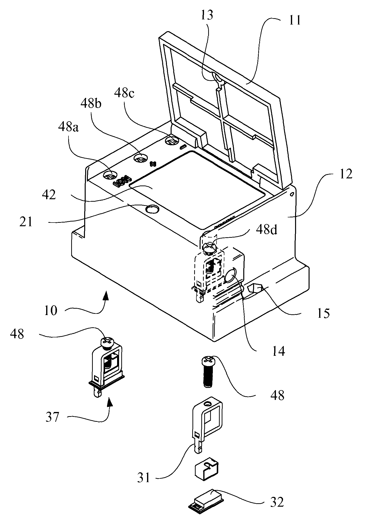
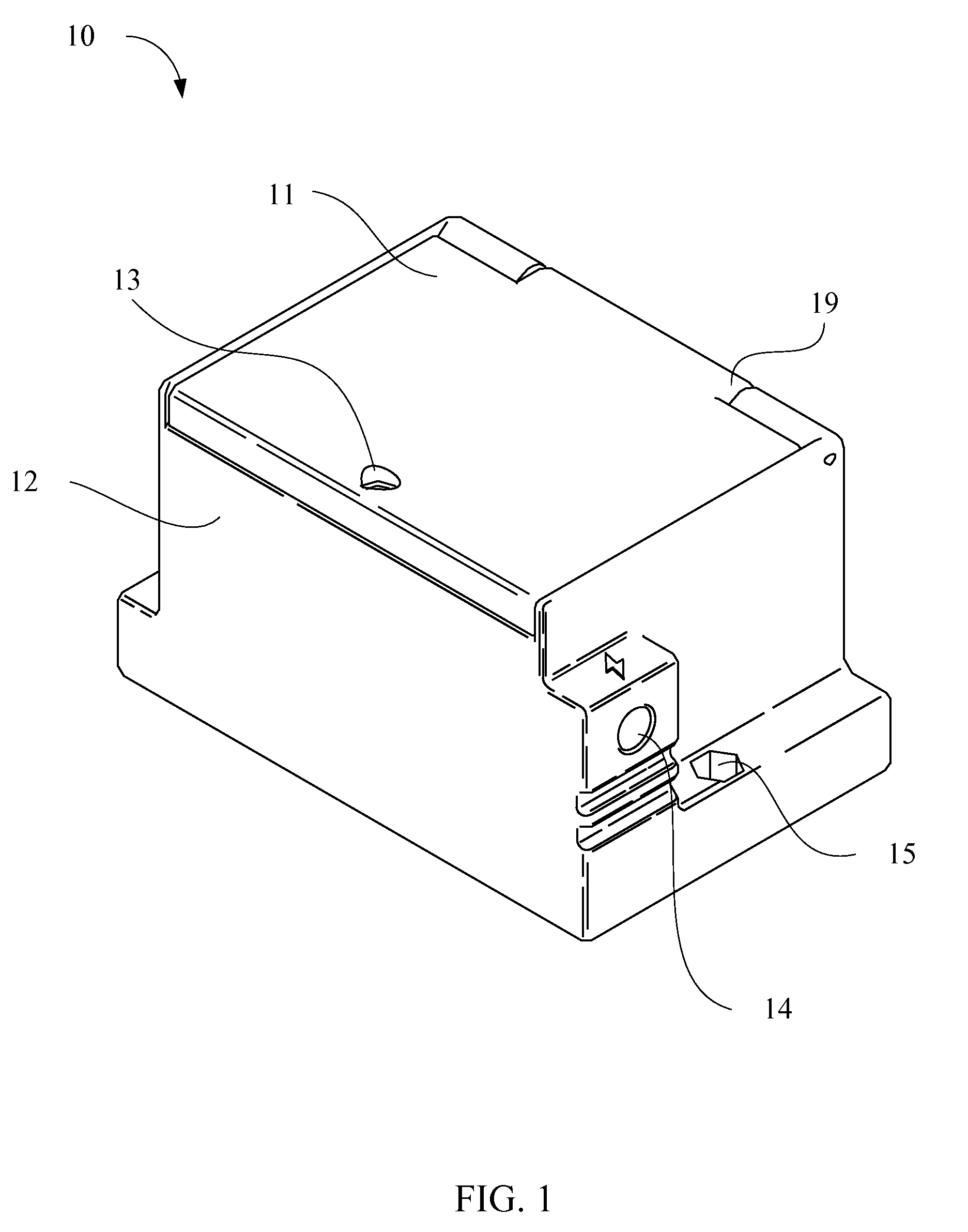
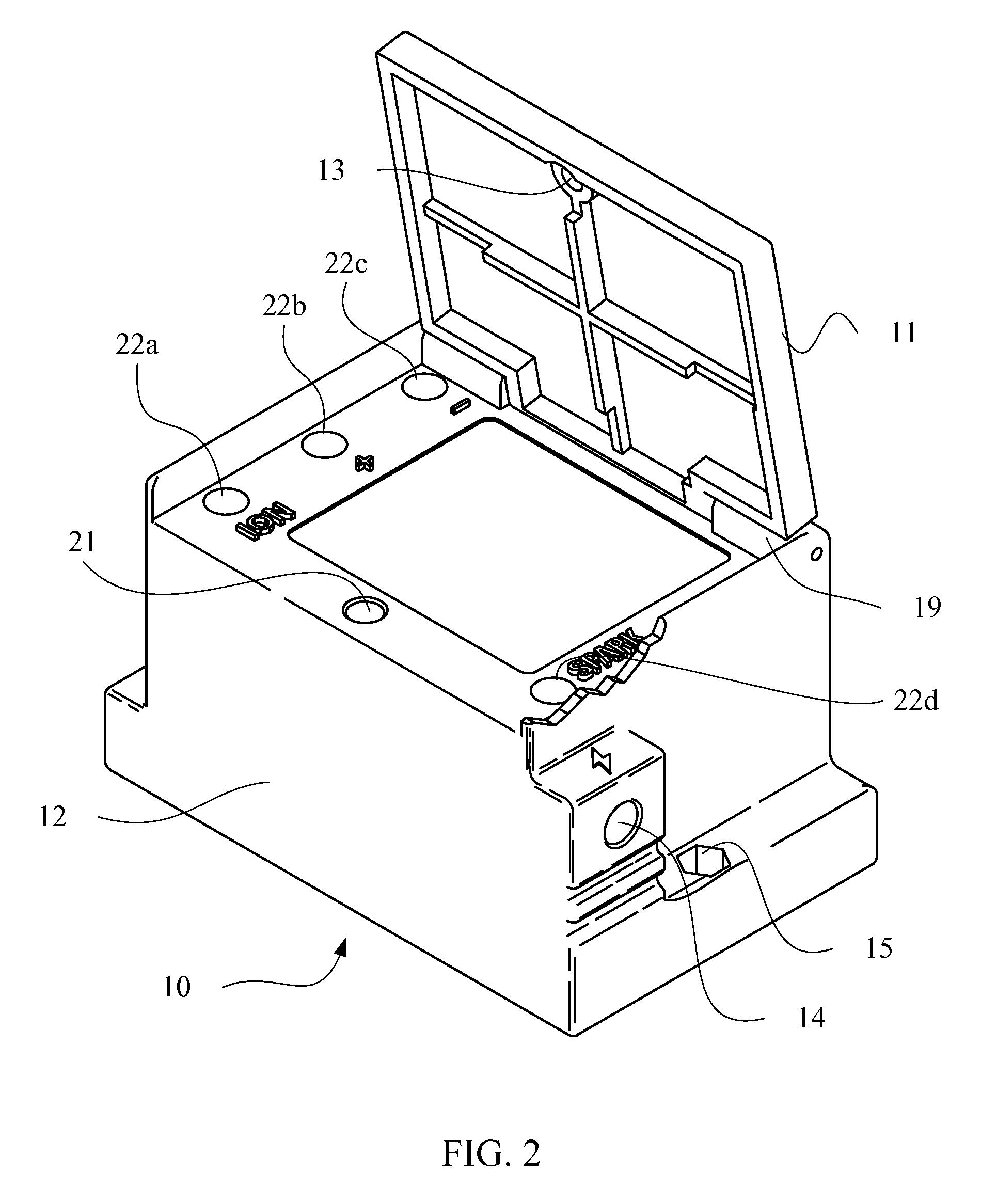
[0038]Referring now to FIG. 1. a perspective view of a coil housing 10 for a coil system in accordance with the present invention is shown. As seen in FIG. 1, the coil housing 10 may comprise a housing lid 11 and a primary housing 12, wherein the housing lid 11 may be disposed on the primary housing 12. The housing lid 11 and the primary housing 12 may be made of any non-conductive material, including non-conductive plastics, polymers, or composite materials. The housing lid 11 and the primary housing 12 may be made using injection molding, machining, and any other methods commonly used by those skilled in the art for making articles of non-conductive mater...


PUM

PropertyMeasurementUnit
combustionaaaaaaaaaa
non-conductiveaaaaaaaaaa
conductiveaaaaaaaaaa

Abstract

A coil system for a burner management system and coil housing is provided having recessed terminals and a housing lid to cover the terminal recesses for reducing exposure of coil system terminals to air and unwanted contacts.

Description

PRIORITY[0001]The present application claims the benefit of U.S. Provisional Patent Application Ser. No. 61 / 674,321 filed on Jul. 21, 2012, which is incorporated herein by reference in its entirety.FIELD OF THE INVENTION[0002]The present invention relates to coil housings for coil systems used to initiate combustion or flame in a combustion management system. More specifically, the present invention relates to coil housings for transformer coils used in a combustion management system for oil or gas vessel heating systems.BACKGROUND[0003]Oil and gas within tanks, or vessels, placed at or near oil and gas wells are commonly heated as part of a preliminary refinement process using heating systems and a combustion management system. The combustion management systems are generally used to heat and monitor a medium drawn through a heating vessel. The combustion or flame used in this process occurs in a combustion chamber near an airplate.[0004]The ability to control combustion or flame ig...

Claims


Application Information

Patent Timeline
Patent Type & Authority Patents(United States)
IPC IPC(8): H01F27/02H01F38/12H01F27/29
CPCH01F38/12H01F27/29H01F27/02
Inventor HATCH, JUSTIN W.
Owner PROFIRE ENERGY
Why Eureka
Try Eureka