
Method and system for obtaining an extended-depth-of-field volumetric image using laser scanning imaging

a laser scanning and depth of field technology, applied in the field of laser scanning imaging systems, can solve the problems of reducing the acquisition speed of thick or bulky samples, loss of temporal resolution which may not be suitable, and inability to apply laser scanning microscopy

Active Publication Date: 2015-12-01
UNIV LAVAL
View PDF16 Cites 14 Cited by
  • Summary
  • Abstract
  • Description
  • Claims
  • Application Information

AI Technical Summary

Benefits of technology

The system achieves a significantly extended depth of field, enhancing temporal resolution and reducing optical power loss, allowing for faster acquisition of volumetric images from a single two-dimensional scan, suitable for dynamic biological studies.

Problems solved by technology

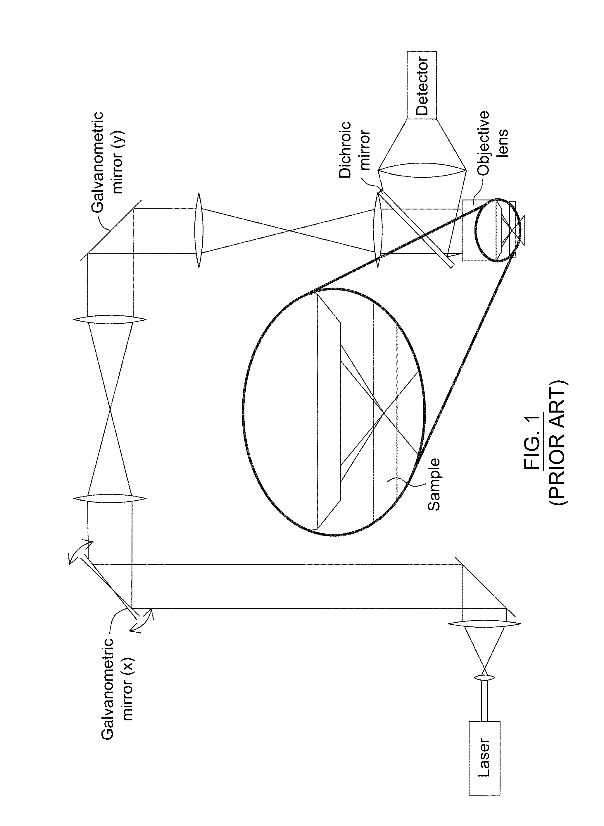
Yet, despite the benefits of the optical sectioning capabilities and the increased spatial resolution achievable by two-photon laser scanning microscopy, the point illumination principle used in this technique reduces the acquisition speed for thick or bulk samples, since a stack of images taken at different depths must be acquired and added.
Optical sectioning thus leads to a loss of temporal resolution which may not be suitable when investigating dynamic biological processes for which temporal resolution may be more important than axial resolution.
However, it cannot be applied to laser scanning microscopy and relies on numerical post-treatment.
The depth of field extension is limited by defocus aberration, which degrades image resolution for large variations in depth.
Furthermore, in some cases, the acquired images are blurry and must be treated by digital processing before obtaining the effective resolution.
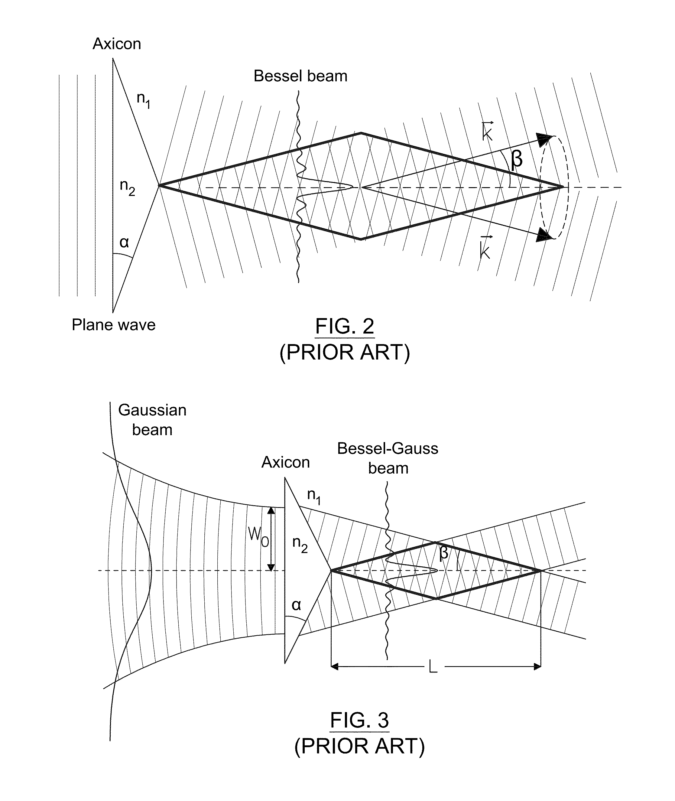
However, limitations of this approach include a slow scan rate arising from the need to displace the axicon mechanically, an absence of a proper working distance, a less-than-optimal fluorescence collection, and difficulties in fabricating defect-free large-angle conical lenses and in adjusting the depth of field.
However, scanning the excitation beam in the plane of the sample is considered only along one axis and the system does not include collection and detection of fluorescence.
Moreover, while providing a laser scanning microscope based on their design considered, several problems are anticipated, most notably optical aberrations at large scanning angles and low-contrast images due to the side lobes of the Bessel beam.
However, this system poses severe constraints on the mechanical alignment and the fabrication tolerance error of the conical lenses.
This filtering process leads to a loss of 25% of the optical power and requires two additional lenses.

Method used


Image

  • Method and system for obtaining an extended-depth-of-field volumetric image using laser scanning imaging
  • Method and system for obtaining an extended-depth-of-field volumetric image using laser scanning imaging
  • Method and system for obtaining an extended-depth-of-field volumetric image using laser scanning imaging

Examples


experimental demonstrations

[0142]Experimental demonstrations illustrating the depth-of-field extension capabilities provided by embodiments of the invention will now be described. As one of ordinary skill in the art will understand, the present invention is not limited to these particular experimental demonstrations.

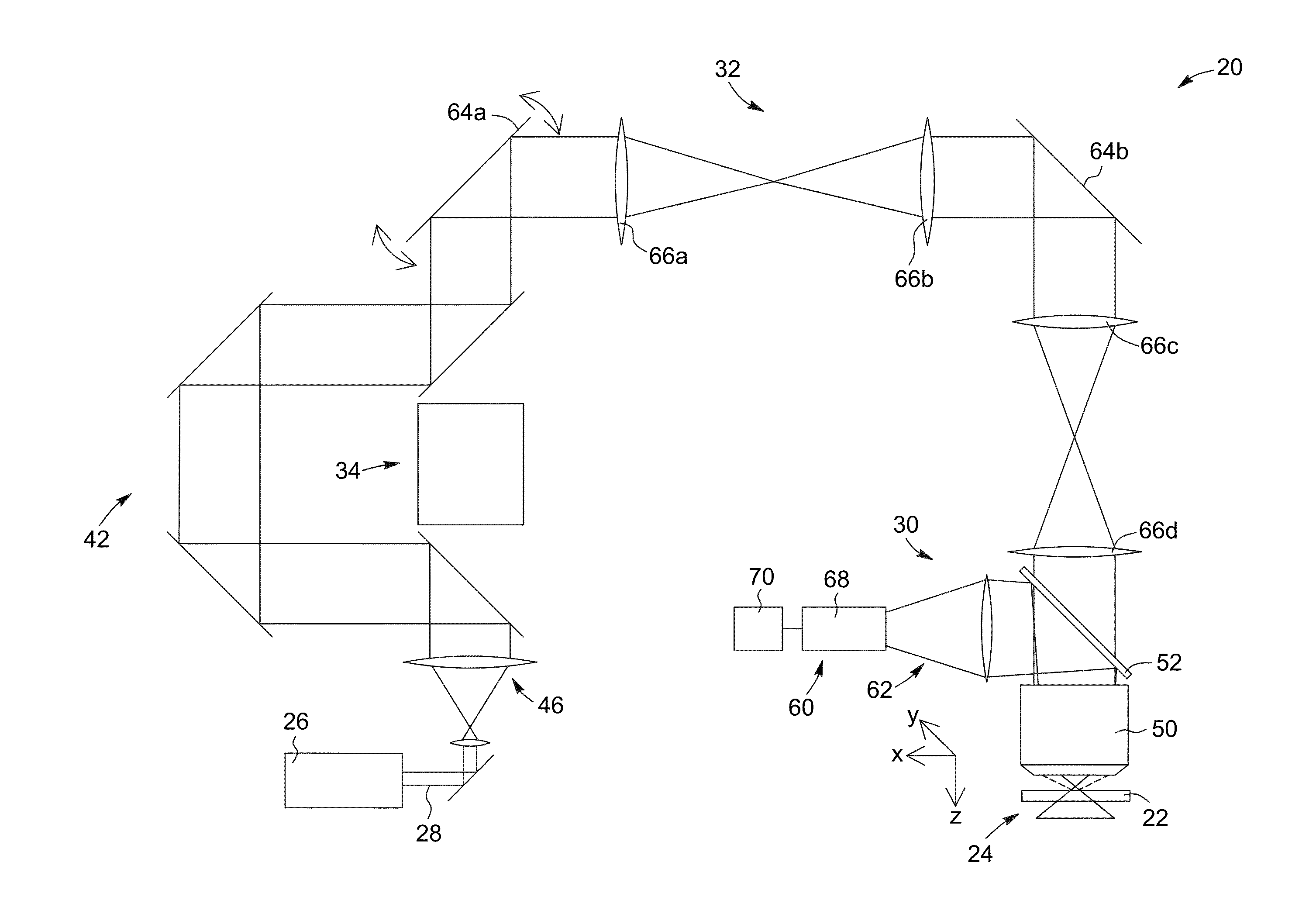
[0143]The experimental demonstrations described below were performed with a home-built laser scanning imaging system configured for two-photon microscopy. The home-built system allows for the insertion of a beam shaping module between the laser module and the entrance of the scanning module.

[0144]The laser module includes a Ti:sapphire laser [Mira, Coherent (trade name)] with a maximum available power of 900 milliwatts, tuned to a central wavelength of 850 nanometers (nm) in a mode-locked regime. The beam shaping module includes an axicon and a Fourier-transform lens. The axicons are uncoated UVFS conical lenses with angles α=2.5 degrees and α=5 degrees fabricated by Altechna (trade name) were use...


PUM

PropertyMeasurementUnit
depth of fieldaaaaaaaaaa

Abstract

A laser scanning imaging system and method for obtaining an extended-depth-of-field image of a volume of a sample are provided. The system includes a laser module generating an input laser beam, a beam shaping module including an axicon and a Fourier-transform lens, and an imaging module including an objective lens and a detecting assembly. The axicon, Fourier-transform lens and objective lens are formed and disposed to successively convert the input laser beam into an intermediate non-diffracting beam, an intermediate annular beam, and an excitation non-diffracting beam. The excitation beam is projected onto the sample and has a depth of field and transverse resolution together defining a three-dimensional excitation region. The detecting assembly collects electromagnetic radiation from the excitation region to obtain one pixel of the extended-depth-of-field image. The system further includes a two-dimensional scanning module for scanning the excitation beam over the sample and build, pixel-by-pixel, the extended-depth-of-field image.

Description

RELATED PATENT APPLICATION[0001]This application incorporates by reference, in its entirety, and claims priority to U.S. provisional patent application Ser. No. 61 / 664,452, filed Jun. 26, 2012.FIELD OF THE INVENTION[0002]The present invention relates to the field of laser scanning imaging systems such as the type used in microscopy, and more particularly concerns a method and a system for extending and possibly adjusting the depth of field in optical laser scanning microscopy.BACKGROUND OF THE INVENTION[0003]Progress in optical microscopy has led to the emergence of a wide range of systems for fluorescence imaging of biological samples. For example, confocal [“Microscopy apparatus”, U.S. Pat. No. 3,013,467 to Minsky] and two-photon [Denk et al., “Two-Photon Laser Scanning Fluorescence Microscopy”, Science vol. 48, p. 73-76 (1990)] laser scanning fluorescence microscopes having better spatial resolution than conventional wide-field microscopy are now commonly employed for imaging nar...

Claims


Application Information

Patent Timeline
Patent Type & Authority Patents(United States)
IPC IPC(8): G01N21/64G02B21/00G02B26/10
CPCG01N21/64G01N21/6458G02B26/105G02B26/101G02B21/002
Inventor THERIAULT, GABRIELLEDE KONINCK, YVESMCCARTHY, NATHALIE
Owner UNIV LAVAL
Learn More