Steering head

a steering head and head technology, applied in the direction of directional drilling, surveying, borehole/well accessories, etc., can solve the problems of limited vertical adjustment, inability to adjust the position of the steering head along a horizontal axis in these prior art steering heads, and the projection of the steering head can often not be completely closed, so as to improve the efficiency of the boring operation, the effect of efficient change of direction and more maneuverability in soil

Active Publication Date: 2015-11-10
VERMEER MFG CO
View PDF24 Cites 3 Cited by
  • Summary
  • Abstract
  • Description
  • Claims
  • Application Information

AI Technical Summary

Benefits of technology

[0010]The steering head is innovative in that the powered actuator may be mounted to the first flap face of the steering flap and the body surface of the steering head's body. When operative, the powered actuator may extend the first flap face into the extended position, thereby enabling the steering head to change the direction of its cutting path. In the extended position, the steering flap will encounter frictional resistance forces with the soil wall, thereby causing the lead edge of the steering head to move in a direction opposing the extended steering flap. For example, if a steering flap on the right side of the steering head is extended, the lead edge of the steering head will tend to move in a direction toward the left through the soil. These same frictional resistance forces will cause the lead edge of the steering to tend to move in an upward direction in the soil with a steering flap extended on the bottom of the steering head. Once the desired alignment has been achieved, the powered actuator may then be deactivated. This in turn uniquely enables the biased hinge at the hinge end of the steering flap to automatically retract the steering flap into a completely closed position by operation of the spring action of the biased hinge with the assistance of the frictional impact forces of the soil wall pushing on the steering flap. This configuration uniquely allows the steering head to be more maneuverable and therefore easier to steer through a desired cutting path in the soil, along both vertical and longitudinal axes. The steering head is therefore able to operate more efficiently, thereby reducing the amount of time spent and power consumed in the boring operation on a project. Furthermore, as the steering flap may be automatically closed at the hinge end by the biased hinge, the steering flap may be less likely to be deformed or allow soil to enter the steering head underneath a steering flap in the extended position. Accordingly, the steering flap may not sustain damage as frequently during the boring operation and its longevity may therefore be increased.
[0015]As discussed above, this configuration uniquely enables the steering head to be more maneuverable in soil and therefore more efficient in its boring operation. The plurality of steering flaps may enable an efficient change of direction of the steering head toward the desired cutting path. For example, if a steering flap on the right side of the steering head is extended, a steering head on the left side of the steering head may be retracted, thereby steering the lead edge of the steering head toward the left. Likewise, these same frictional resistance forces will cause the lead edge of the steering to tend to move in an upward direction in the soil with a steering flap extended on the bottom of the steering head and retracted on the top of the steering head. With the deactivation of the powered actuator on a steering flap, the configuration of the spring action on the biased hinge of each deactivated steering flap uniquely enables these steering flaps to uniformly retract with the assistance of the frictional impact forces of the soil wall on the steering flaps. This configuration may therefore improve the efficiency of the boring operation and the longevity of the steering head.
[0022]The combination of an altitude sensor and one or more positional sensors may uniquely enable the steering head to be accurately positioned in the desired cutting path of the soil, along vertical and horizontal axes. The information gathered by the altitude sensor and the positional sensors may therefore indicate when one or more of the steering flaps should be extended or retracted, depending on the position of the steering head in reference to the desired cutting path.
[0024]In another embodiment of the present disclosure, the steering head may further include one or more shields laterally disposed on the first flap face of the steering flap adjacent to the outer tube. The shields may be operative to prevent soil from entering beneath the steering flap in the extended position and to provide support to the steering flap. In another embodiment, a center rib may be disposed proximate to the shields operative to provide additional support to the steering flap.

Problems solved by technology

However, the position of the steering head along a horizontal axis cannot be adjusted in these prior art steering heads.
Furthermore, the amount of vertical adjustment is limited by the amount of torsion that can be applied to the nut and bolt configuration.
However, the projections on these steering heads can frequently not be completely closed.
As a result, the frictional and impact forces between the projections and the surrounding soil wall, as well as the penetration of soil under these projections, reduces the efficiency of operation and maneuverability of these steering heads.
As such, it is possible for the steering head to cause the boring operation to follow an undesirable path.
This can result in increased labor and utility costs than were budgeted for a project.
Furthermore, it is understood that the repeated impact between the steering head projections and the soil wall may deform these projections, thereby damaging the steering head and reducing its operational efficiency, resulting in added equipment and repair costs.
In order to partially offset the occurrence of deformation, it is understood that these prior art steering head projections could be partially closed manually, a process that again reduced the efficiency of the boring operation.

Method used


Image

  • Steering head
  • Steering head
  • Steering head

Examples


Embodiment Construction

[0040]Reference will now be made in detail to presently preferred embodiments of the invention, one or more examples of which are illustrated in the accompanying drawings. Each example is provided by way of explanation, not limitation, of the invention. In fact, it will be apparent to those skilled in the art that modifications and variations can be made in the present invention without departing from the scope and spirit thereof. For instance, features illustrated or described as part of one embodiment may be used on another embodiment to yield a still further embodiment. Thus, it is intended that the present invention covers such modifications and variations as come within the scope of the appended claims and their equivalents.

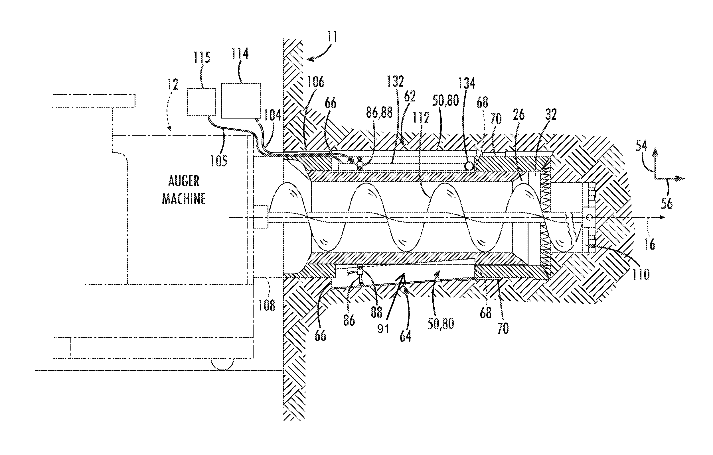
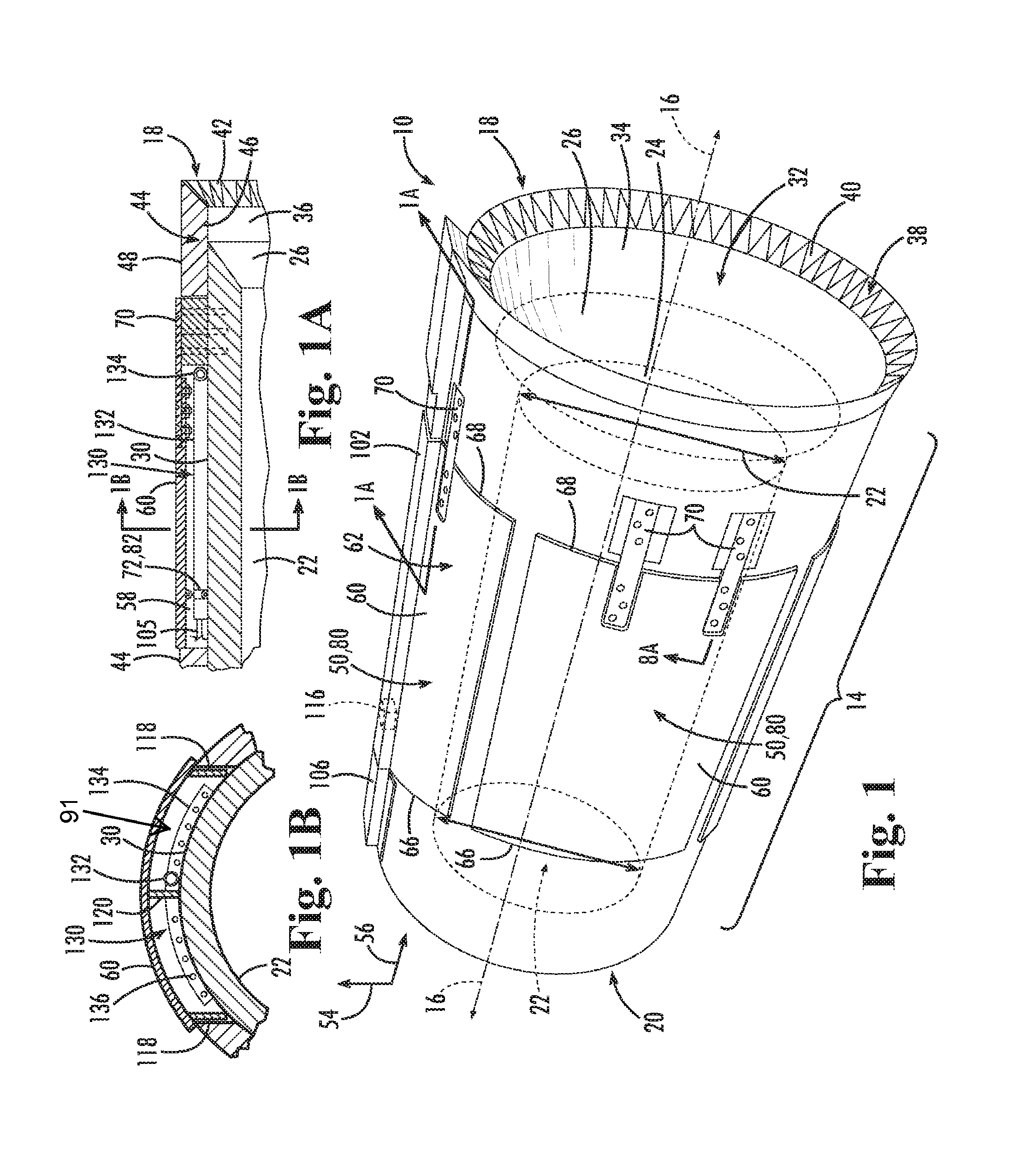
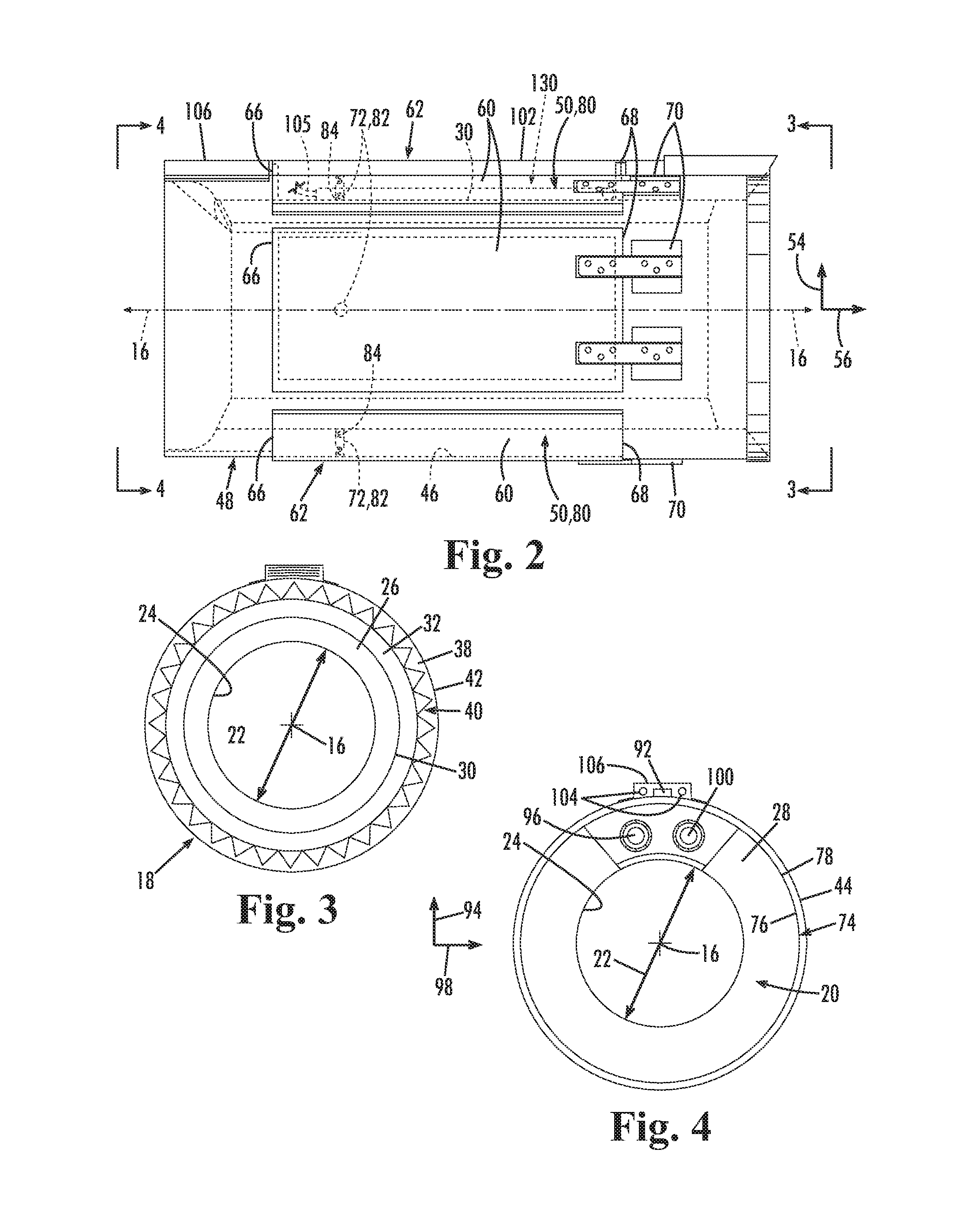
[0041]FIGS. 1 through 6 show an embodiment of the steering head 10 having a generally cylindrical body 14 defining a longitudinal body axis 16. The body 14 has a first body end 18 and an opposing second body end 20. The second body end 20 of the steering hea...


PUM


Abstract

A steering head for use with a casing, the steering head having a body with a first body end with a lead edge, a second body end with a rear edge, and a body surface extending from the lead edge to the rear edge, an outer tube with an internal side generally facing the body surface, the outer tube extending from the first body end to the second body end, and a steering flap disposed on an external side of the outer tube having a first flap face facing radially inwardly and a second flap face facing radially outwardly. A fluid dispenser is disposed in a void defined between the outer tube and the body.

Description

FIELD OF THE INVENTION[0001]The present disclosure relates generally to a steering head for use with an auger for boring through soil.BACKGROUND[0002]Underground dredging and boring operations are necessary for the laying of underground utility lines (e.g. water, sewer, and power). The boring or tunneling of the soil to clear a path for such underground utility lines requires the use of a steering head, a casing, an auger unit, and an auger machine. The casing is typically weldably mounted to the steering head at one end and engaged to the auger machine at the opposite end, with an auger unit extending from the auger machine through the casing and into the steering head. The auger machine rotates the auger, thereby enabling the auger unit to perform the boring or tunneling operation through the surrounding soil. The auger removes the soil through the steering head and into the auger machine. As the bore hole is lengthened, additional sections of casing are welded to previously laid ...

Claims


Application Information

Patent Timeline
Patent Type & Authority Patents(United States)
IPC IPC(8): E21B7/06E21B10/44E21B7/00E21B7/20
CPCE21B7/062E21B7/005E21B7/20E21B10/44E21B47/024
Inventor MALCOLM, WILLIAM
Owner VERMEER MFG CO
Why Eureka
Try Eureka