
Rotating and oscillating breaching device with reactive material

a technology of reactive materials and rotating oscillating devices, which is applied in the direction of aluminum-thermic welding apparatus, manufacturing tools, non-electric welding apparatus, etc., can solve the problems of difficult application on other than flat surfaces, unwieldy, etc., and achieve the effect of less effective cutting action of rm

Active Publication Date: 2015-11-03
BARNETTE DARREL +1
View PDF48 Cites 1 Cited by
  • Summary
  • Abstract
  • Description
  • Claims
  • Application Information

AI Technical Summary

Benefits of technology

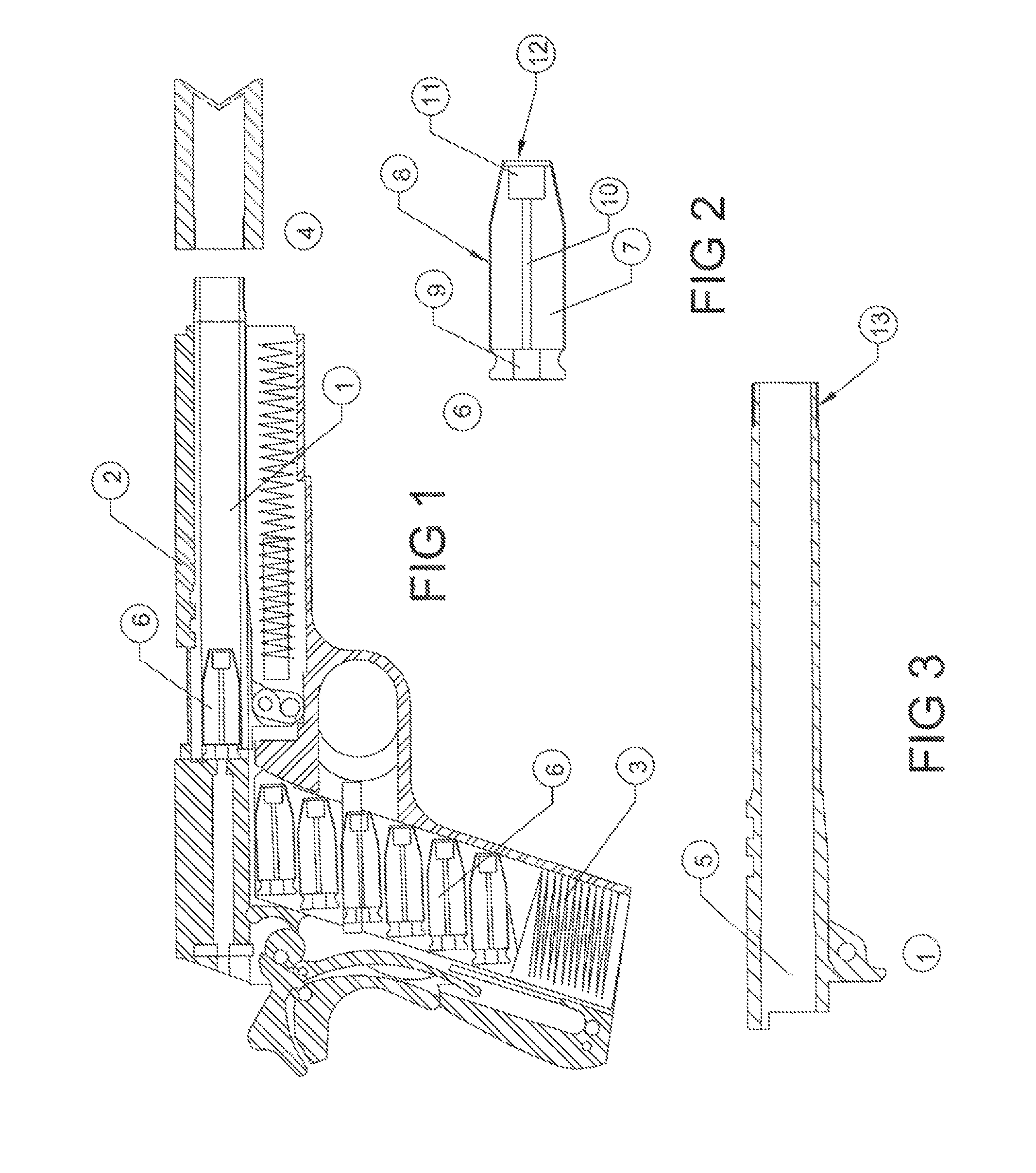
[0013]Other embodiments, while useful for RM, improve the firearm itself. The first embodiment is a cartridge that is fed into the breech from the gun's magazine or clip when the muzzle is temporarily fitted with a cutting or welding nozzle. In this case, the gun's breech, barrel and detachable nozzle should be manufactured from heat resistant material such as ceramic, or at least its bore may be fabricated of such material, including the option of using a composite, and / or a ceramic-composite combination, provided such material is either or both of refractory and insulative (at least in comparison to metal).
[0015]The present invention is also a breaching device that may be used to create a linear and, if desired, continuous, cut or breach in a metal structure. The cut or breach created may be non-linear in shape and not deviate from the functionality of the device. The device includes a plurality of containers joined together, such as by a metal wire or the like to form a series of cutting charges. One or more of the containers includes Reactive Material (RM) that may be ignited electronically or some other activation mechanism. The containers that do contain RM are sealed with the RM therein and preferably fabricated to be sufficiently heat resistant so that the RM is only ignited intentionally. The RM that is contained in the containers may be fired simultaneously, sequentially or in a programmed pattern, depending on the requirements of the application. The breaching device may be used to control the breaching of a structure under a wide range of conditions. For example, conventional explosive “linear shaped charges” that exist for underwater and above water breaching can be used to open a substrate, these existing devices must be activated remotely so as to prevent harm to any person operating it. They can also be unwieldy and difficult to apply on other than flat surfaces. The present invention, on the other hand, is manageable under different conditions and the operator can be close at hand to activate it as the energy generated with the device is substantially completely directed to the substrate to be breached and the possibility of an adverse condition resulting from a shock wave, for example, is minimized.
[0016]The embodiment of the invention described above for breaching generally contemplates that the breaching device remains in a fixed location on the substrate to be breached. In an embodiment of the invention suitable for use in the removal of underwater structures, such as required under the IDLE IRON program, the breaching device is configured to rotate and / or oscillate. Specifically, the rotating / oscillating reactive material breaching device of the present invention is configured to cleanly cut the thick-walled, large diameter legs of an oilrig non-explosively using (RM). It will cut from the inside to the outside, which is necessary when cutting below the mud line, as required by law. Because this device is non-explosive, barges and boats can be tied alongside the platform and exposed workmen and equipment are not at risk.
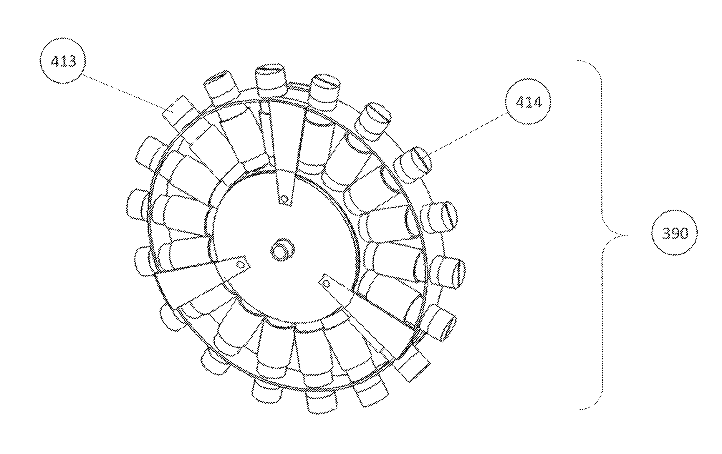
[0017]The device incorporates RM feed assemblies that contain RM and that are radially mounted on an inner and outer ring that are incorporated into a hub assembly. Each RM feed assembly containing the RM is spring mounted or otherwise configured for extension and retraction so that each RM feed assembly is held in a retracted position to reduce the overall, diameter of the device during the initial insertion into the substrate to be cut, such as the leg of an oil platform, for example. Centrifugal force generated during spin up of the device will cause the RM feed assemblies to extend outward to reduce the gap between the RM feed assemblies' nozzles and the substrate to be cut. A step may be included as part of the RM feed assembly body, which step prevents the RM feed assembly from sliding out too far.
[0019]Breaching a thick substrate will require the use of a large amount of RM relative to that which is required to breach a thinner substrate. Typically, the RM burn is initiated close to the interior side of the nozzle, and the burning of the RM propagates away from the nozzle in a planar front. The further away the planar front moves from the nozzle, the less effective the cutting action of the RM becomes. It may therefore be necessary to provide a means to feed the RM within the RM feed assemblies toward the nozzle during the burn. This means may be accomplished via centrifugal force acting on the RM as a result of spinning of the ring or via a cartridge actuated gas-generating device to provide pressure to the rear of the RM to move it outward, or by adding a mass, such as lead shot, to the rear of the RM to generate additional radial force on the RM.

Problems solved by technology

They can also be unwieldy and difficult to apply on other than flat surfaces.

Method used


Image

  • Rotating and oscillating breaching device with reactive material
  • Rotating and oscillating breaching device with reactive material
  • Rotating and oscillating breaching device with reactive material

Examples


second embodiment

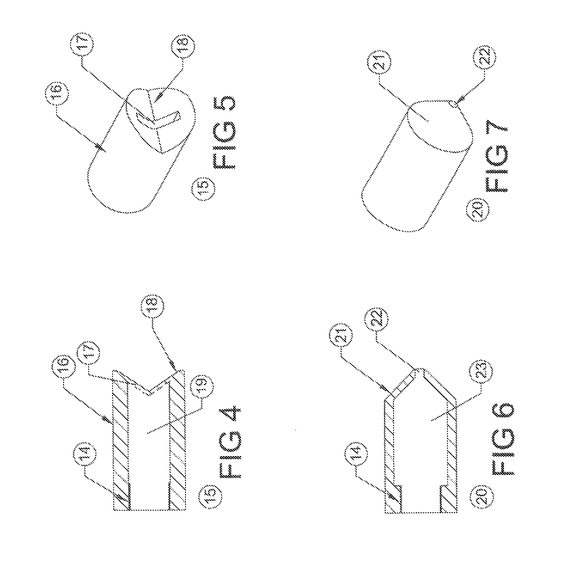
[0055]a cutting / welding device of the present invention is shown in FIG. 8 as a gun. The gun and / or components and variants of components thereof are shown in FIGS. 8-12 and include the gun barrel 1, the breech 5, a muzzle loading cutting component 24, a heat resistant tube 26, an impact-initiated primer 27, a cutting nozzle 28, an inert breech plug 29, a nozzle plug 30, which may be frangible or ablative, a muzzle loading tack welding device 31, the RM 7, the hollow flame tube 10, the RM ignition initiator 11, the slot opening 17 for the cutting component 24, and the pointed end 21 and the internal chamber 23 for the muzzle loading tack welding device 31.

[0056]The heat resistant tube 26 is configured to extend substantially the entire length of the gun barrel 1 and extending through the breech 5, is fitted with a center fire primer 27 or impact initiated electronic device at the point where the gun's hammer can ignite the device corresponding in that manner to the operation of the ...

first embodiment

[0059]As seen in FIG. 10, the tube 26 is elongate with the nozzle 28 affixed thereto. The end of the device 24 that extends into the breech is provided with the primer 27 that is exploded into the flame tube 10 that extends longitudinally through the center of the device 24 and prevents the ignition of the surrounding RM 7. At the muzzle end of the device 24, and behind the cutting nozzle 28 is the RM Initiator 11 that activates the RM 7. As described in the first embodiment above, the nozzle 28 has a cylindrical outer shape with the V shaped or concave front face 18 with the slot 17 situated 90° through the center of the face 18. The slot 17 may be plugged with plug 30, which may be a frangible or ablative material to protect the interior of the device 24 from environmental hazards during storage.

[0060]Like the previously described embodiment, the cutting nozzle 28 may have a slotted or some other configuration designed to increase the cutting efficiency of the torch established up...


PUM

PropertyMeasurementUnit
stress concentrationsaaaaaaaaaa
heat resistantaaaaaaaaaa
rotationaaaaaaaaaa

Abstract

A breaching device for non-explosively cutting through a substrate, such as the leg of an offshore oil platform or other large cylinder from within the leg or large cylinder. The device includes a ring and a plurality of Reactive Material (RM) feed assemblies. Each RM feed assembly is arranged around the ring and includes an extendible nozzle. Each RM feed assembly includes a cavity that may contain RM that when ignited exits the nozzle. The nozzles are spring loaded and arranged to extend toward the inner surface of the substrate to be cut when the ring is rotated and / or oscillated. This arrangement results in a substantially uniform cut of the substrate from within with much less danger, material, equipment and cost than is currently required to remove large water-based structures.

Description

CROSS-REFERENCE TO RELATED APPLICATION[0001]This application is a continuation-in-part and claims the priority benefit of U.S. patent application Ser. No. 13 / 747,596 filed Jan. 23, 2013, entitled REACTIVE MATERIAL BREACHING DEVICE, now U.S. Pat. No. 8,789,468 issued Jul. 29, 2014, which is a continuation-in-part and claims the priority benefit of U.S. patent application Ser. No. 13 / 495,058, filed Jun. 13, 2012, now U.S. Pat. No. 8,679,399 issued Mar. 25, 2014, entitled “APPARATUS FOR METAL CUTTING AND WELDING” having a common inventor thereof, which application is a nonprovisional and claims the priority benefit of U.S. provisional patent application Ser. No. 61 / 520,593, filed Jun. 13, 2011, entitled “METAL CUTTING / TRACK WELDING KIT FOR SERVICE SIDEARM OR OTHER GUN.” The entire content of the priority applications is incorporated herein by reference.BACKGROUND OF THE INVENTION[0002](1) Field of the Invention[0003]This invention relates to devices for cutting metal. More particularly...

Claims


Application Information

Patent Timeline
Patent Type & Authority Patents(United States)
IPC IPC(8): F42B3/22B23K20/06B23K7/10B23K7/00B23K23/00F41C9/06
CPCF42B3/22B23K7/00B23K7/10B23K20/06B23K23/00F41C9/06
Inventor BARNETTE, DARRELBLEICKEN, ERIC
Owner BARNETTE DARREL
Learn More