
System and method for countering the effects of microphonics in a phase locked loop

a phase lock loop and microphonic technology, applied in the direction of electrical equipment, pulse automatic control, etc., can solve the problems of degrading or impairing the performance of the pll

Active Publication Date: 2015-10-13
SYMBOL TECH LLC
View PDF19 Cites 0 Cited by
  • Summary
  • Abstract
  • Description
  • Claims
  • Application Information

AI Technical Summary

Benefits of technology

The patent describes a system and method for countering the effects of microphonics in a phase locked loop (PLL) used in electronic devices. The invention identifies a motion indicator based on sensor indicators and adjusts the parameters of the PLL accordingly to prevent degradation in performance caused by mechanical vibrations. The technical effect of the invention is to improve the stability and performance of the PLL in electronic devices.

Problems solved by technology

The change in electrical behavior of components may thus degrade or impair the performance of a PLL.

Method used


Image

  • System and method for countering the effects of microphonics in a phase locked loop
  • System and method for countering the effects of microphonics in a phase locked loop
  • System and method for countering the effects of microphonics in a phase locked loop

Examples


Embodiment Construction

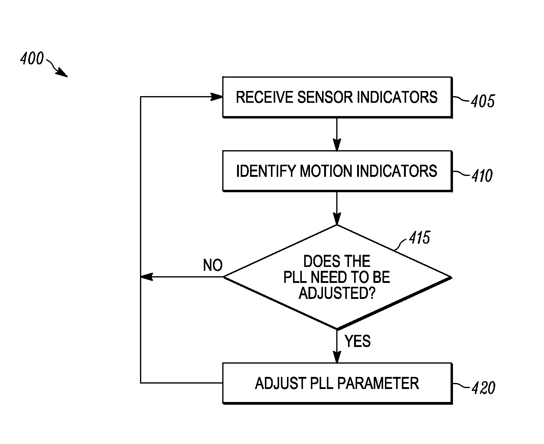
[0011]An apparatus and method of operating an electronic device is provided. In operation, the electronic device receives sensor indicators from at least one sensor. Upon receiving sensor indicators, a motion indicator based on the sensor indicators is identified and a parameter of a phase lock loop (PLL) of the device is adjusted based on the motion indicator, the PLL having at least one component susceptible to microphonics.

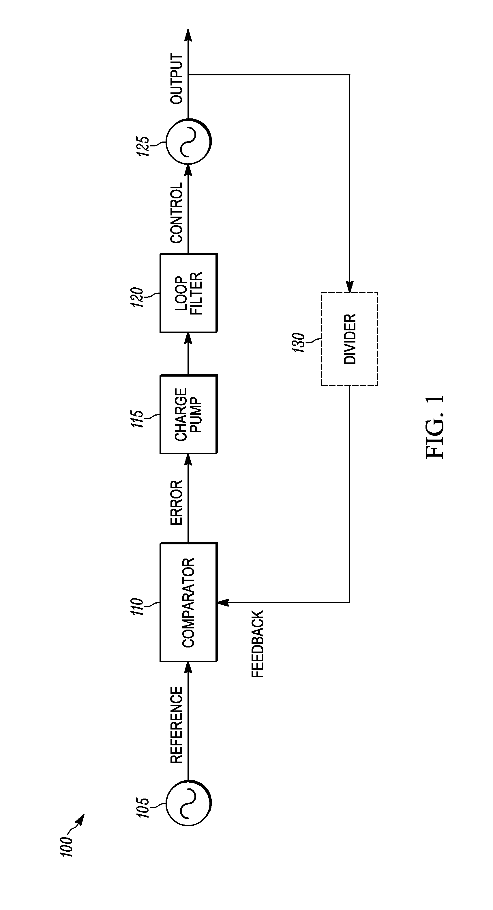
[0012]FIG. 1 is a block diagram of a phase lock loop (PLL) 100 in which methods and components required for a system and method for countering the effects of microphonics in a phase locked loop is implemented in accordance with the embodiments. An oscillator 105 generates a reference signal. A comparator 110 compares two input signals, in this implementation, the reference signal being one input signal and a feedback signal based on the PLL output being the other input signal, and produces an error signal which is proportional to the phase and optionally freque...


PUM


Abstract

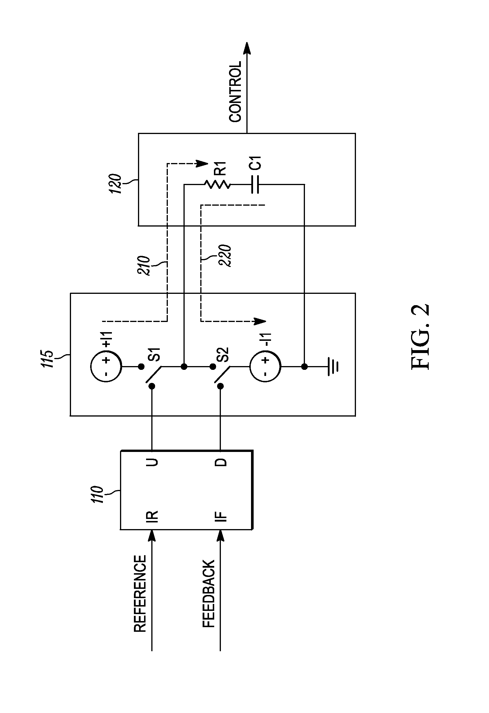
A method and apparatus for operating an electronic device is provided. The electronic device, which includes a phase lock loop (PLL) receives sensor indicators from at least one sensor. Upon receiving sensor indicators, the device identifies a motion indicator based on the sensor indicators. A parameter of the PLL is adjusted based on the motion indicator, the PLL having at least one component susceptible to microphonics. When the PLL includes a charge pump, a parameter that may be adjusted is a pump current of the charge pump. When the PLL further comprises an oscillator for generating a reference signal, the parameter that may be adjusted is a trim of the oscillator.

Description

BACKGROUND OF THE INVENTION[0001]A phase lock loop (PLL) is a control system that generates an output signal whose phase and / or frequency is related to the phase of an input signal. While there are several differing types, in some implementations, a PLL may be formed of an electronic circuit consisting of a frequency oscillator providing a periodic input signal or a reference signal, a controlled oscillator that generates an output signal and a comparator. To enable the comparator to perform a comparison, the output signal is typically fed back toward the reference signal, creating a feedback loop. The comparator thus compares the phase of the reference signal with the phase of the feedback signal and causes the controlled oscillator to be regulated to keep the phase of the reference and output signals synchronized or locked.[0002]The reference and output signal frequencies may also be related. Consequently, in addition to synchronizing signal phases, a phase-locked loop may track a...

Claims


Application Information

Patent Timeline
IPC IPC(8): H03L7/06H03L7/08
CPCH03L7/08H03L7/0891
Inventor KADRI, IRFANNG, CHU PANG ALEX
Owner SYMBOL TECH LLC
Learn More