
Cathode ray tube having a tension mask with microphonics control

A cathode ray tube and shadow mask technology, applied in the field of tensioned shadow mask components, can solve problems such as misregistration of electron beams and abnormal images

Inactive Publication Date: 2005-03-23
THOMSON LICENSING SA
View PDF0 Cites 0 Cited by
  • Summary
  • Abstract
  • Description
  • Claims
  • Application Information

AI Technical Summary

Problems solved by technology

This vibration can cause overall electron beam misregistration on the screen and will cause image anomalies that are not good for CRT viewers

Method used


Image

  • Cathode ray tube having a tension mask with microphonics control
  • Cathode ray tube having a tension mask with microphonics control
  • Cathode ray tube having a tension mask with microphonics control

Examples


Embodiment Construction

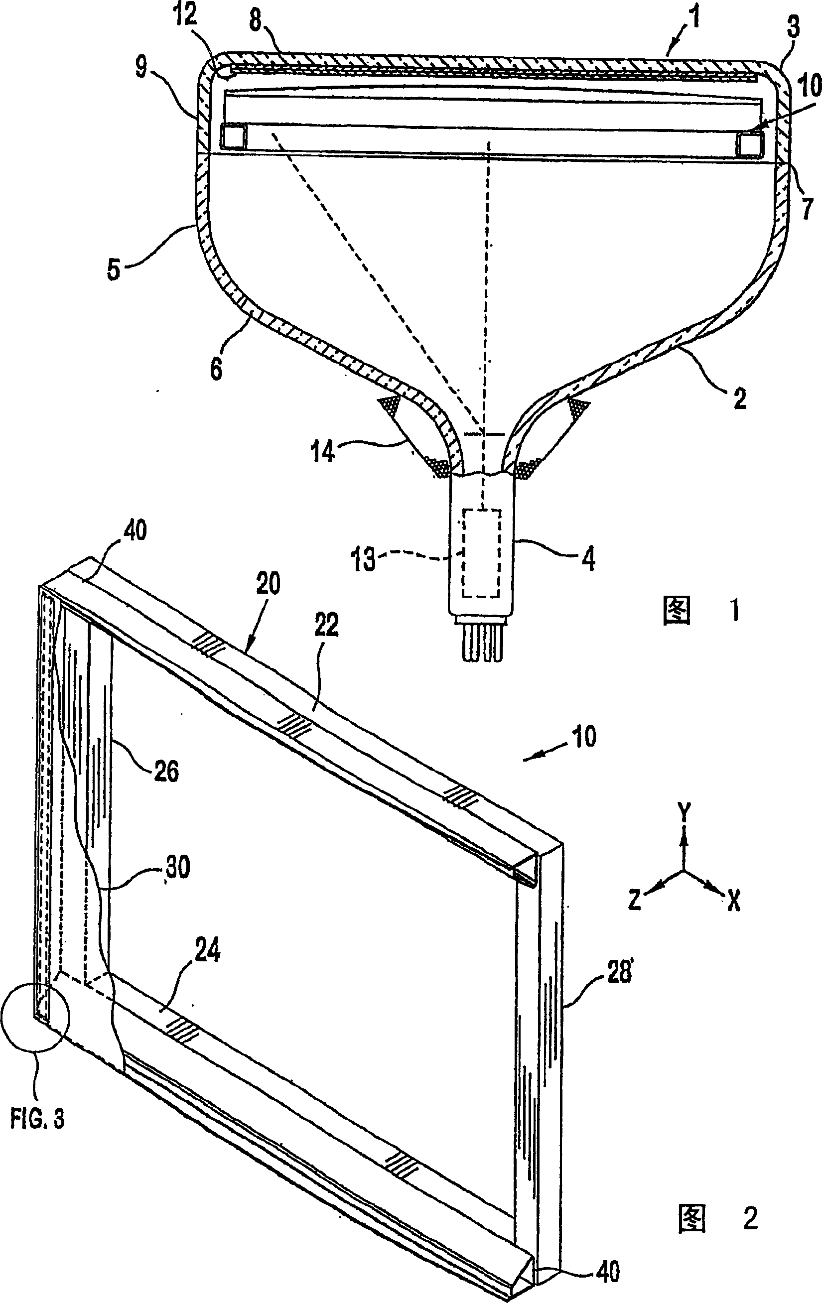
[0011] FIG. 1 shows a cathode ray tube (CRT) 1 having a glass envelope 2 comprising a rectangular front panel 3 and a tubular neck 4 joined by a funnel 5 . The funnel 5 has an inner conductive coating (not shown) extending from the anode switch (or key) 6 towards the front panel 3 and to the neck 4 . The front panel 3 includes a viewing screen 8 and a peripheral flange or side wall 9 sealed to the funnel 5 with glass frit 7 . A three-color phosphor screen 12 is provided on the inner surface of the phosphor screen panel 3 . The screen is a line screen having phosphor lines arranged in triplets, each triplet comprising a phosphor line of one of three colors. The tensioned mask frame assembly 10 is detachably installed at a predetermined distance from the screen 12 . An electron gun 13, shown schematically in dotted line in Figure 1, is mounted in the center of the neck 4 to generate and guide three in-line electron beams along converging paths, a central beam and two side or o...


PUM


Abstract

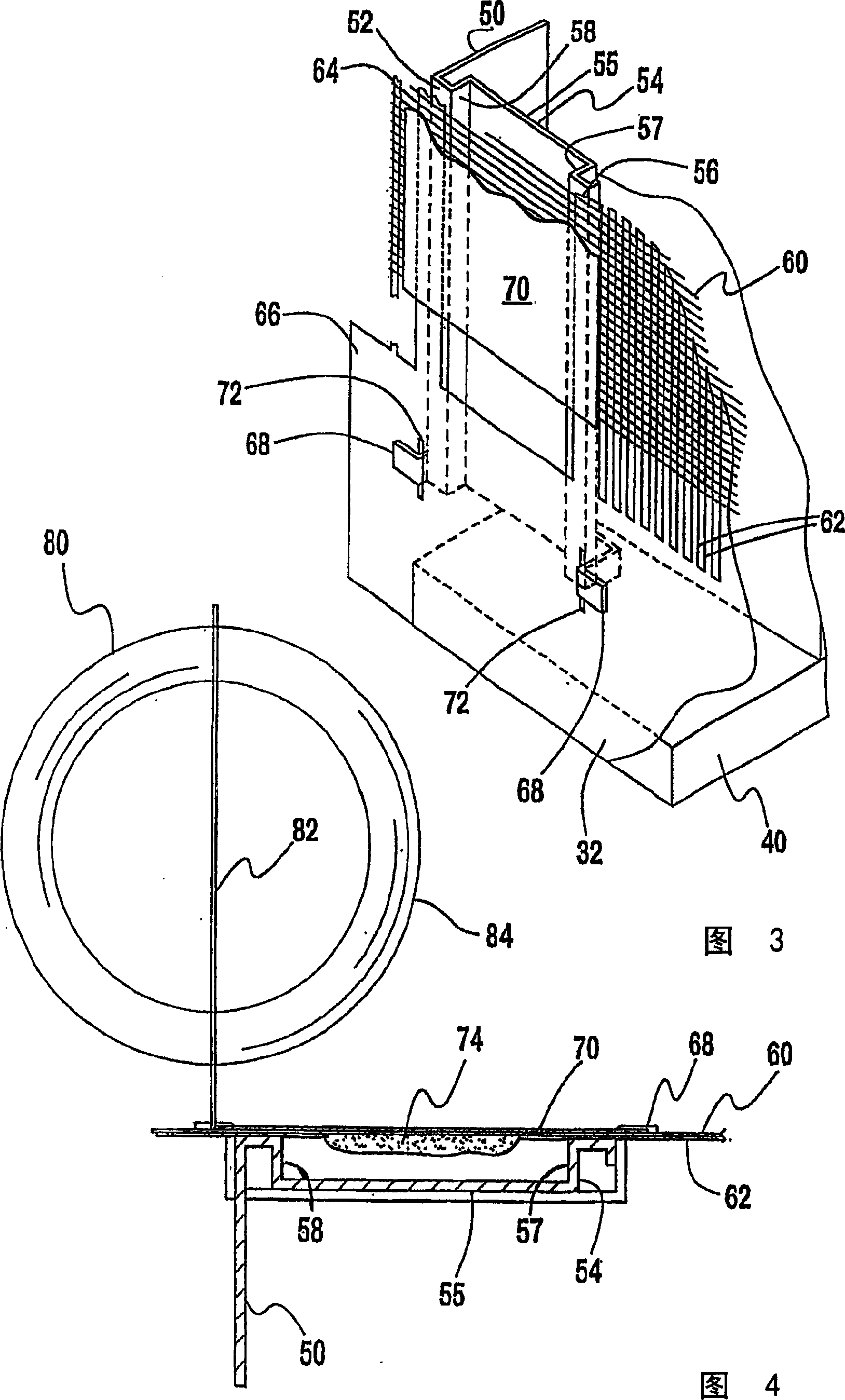
A cathode-ray tube (1) having a luminescent screen (12) on a faceplate panel (3) and a tension mask assembly (10), wherein the assembly comprises a pair of support blades for supporting a tension mask (30). The tension mask has a pair of mask borders (66) each being fixed to a respective support blade and a plurality of strands extending between the mask borders. The mask further comprises cross wires (60) extending generally perpendicular to the strands (62) on a screen facing side and at least one shield assembly (70) extending between and attached to the mask borders. The shield assembly has a sheath (54) extending along one side of the mask in contact with at least one strand and a shield attached to the cross wires of the mask in overlapping relation to the sheath.

Description

technical field [0001] The present invention generally relates to a cathode ray tube having a tensioned shadow mask assembly, and more particularly to a tensioned shadow mask assembly having a vibration damping device. Background technique [0002] A color cathode ray tube, or CRT, includes an electron gun for forming and directing three electron beams to the tube screen. The screen is located on the inside surface of the tube front panel and consists of an array of phosphor elements that emit light of three different colors. A shadow mask, either a formed shadow mask or a tensioned mask with wire harnesses, is located between the electron gun and the screen. A beam of electrons from the electron gun passes through openings in the shadow mask and strikes the screen causing the phosphor to glow so that the image is displayed on the viewing screen on the front panel. [0003] One type of CRT has a tensioned mask that includes a set of wire bundles that are tensioned on the m...

Claims


Application Information

Patent Timeline
Patent Type & Authority Applications(China)
IPC IPC(8): H01J29/07
CPCH01J2229/0744H01J29/07
Inventor J·J·米查尔楚克R·W·诺斯克尔
Owner THOMSON LICENSING SA
Learn More