
Vehicular active noise control system

a technology of active noise control and vehicle, applied in the direction of noise generation, ear treatment, instruments, etc., can solve the problems of long and heavy, vehicle weight as a whole, differential noise, etc., and achieve the effect of reliably cancelling out driveline nois

Active Publication Date: 2008-11-27
HONDA MOTOR CO LTD
View PDF26 Cites 55 Cited by
  • Summary
  • Abstract
  • Description
  • Claims
  • Application Information

AI Technical Summary

Benefits of technology

[0009]It is an object of the present invention to provide a vehicular active noise control system which is capable of reliably canceling out a driveline noise.
[0010]Another object of the present invention is to provide a vehicular active noise control system which is capable of making a vehicle that incorporates the vehicular active noise control system lower in weight and cost.

Problems solved by technology

The noise is generated by the differential because the propeller shaft which is relatively long and heavy is not well balanced upon rotation.
The torsional damper disposed around the propeller shaft for reducing the noise makes the vehicle heavy as a whole and also makes the vehicle costly to manufacture.
These countermeasures, however, are still liable to make the vehicle heavy as a whole and also to make the vehicle costly to manufacture.
However, since the active noise control apparatus is based on the fact that the engine noise is generated in synchronism with the rotation of the output shaft of the engine, and generates the canceling sound using the frequency of the engine rotation signal depending on the rotational speed of the output shaft, the active noise control apparatus cannot directly be applied to reduce the driveline noise.
This is because the engine is occasionally disconnected from a transmission by a lockup control function of an automatic transmission vehicle or a clutch function of a manual transmission vehicle, making it difficult to calculate the rotational speed and rotation frequency of a driveline component such as a drive shaft, a propeller shaft, or the like at all times from the rotational speed of the output shaft of the engine.
Therefore, even if the canceling sound is generated using the frequency of the engine rotation signal, it is difficult to reduce the noise in the passenger compartment (driveline noise) due to the vibratory noise of the driveline.

Method used


Image

  • Vehicular active noise control system
  • Vehicular active noise control system
  • Vehicular active noise control system

Examples


first embodiment

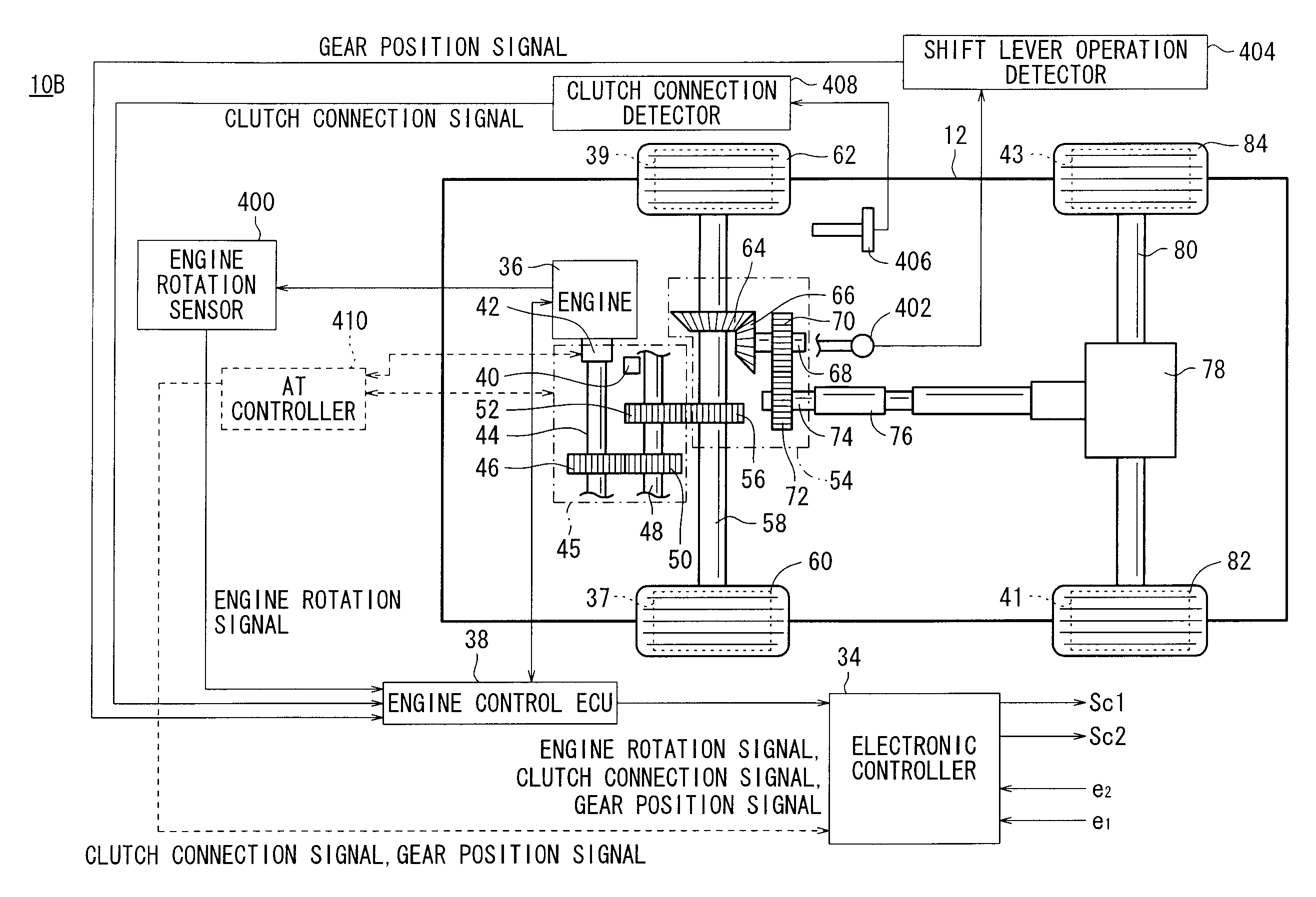
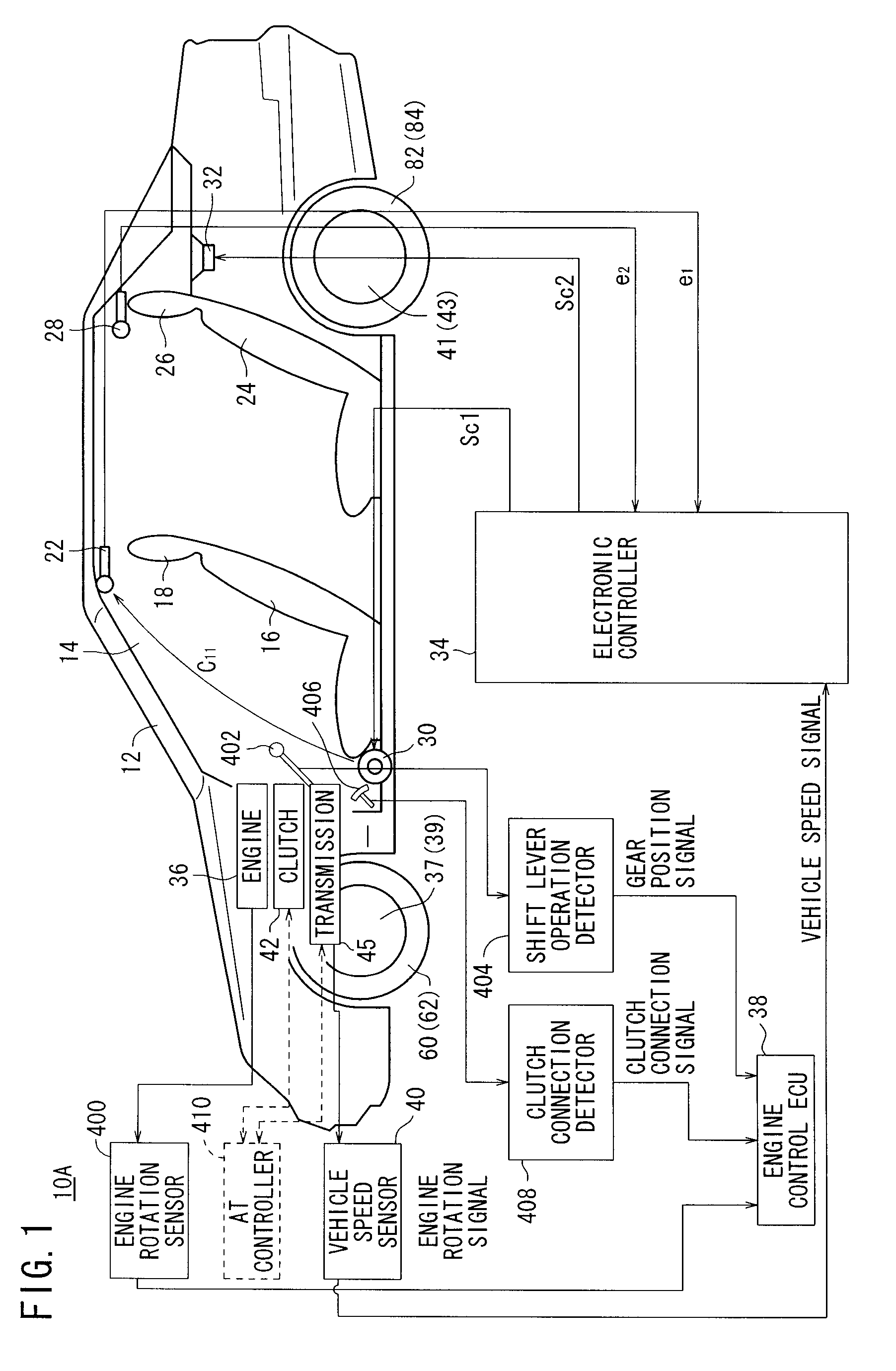
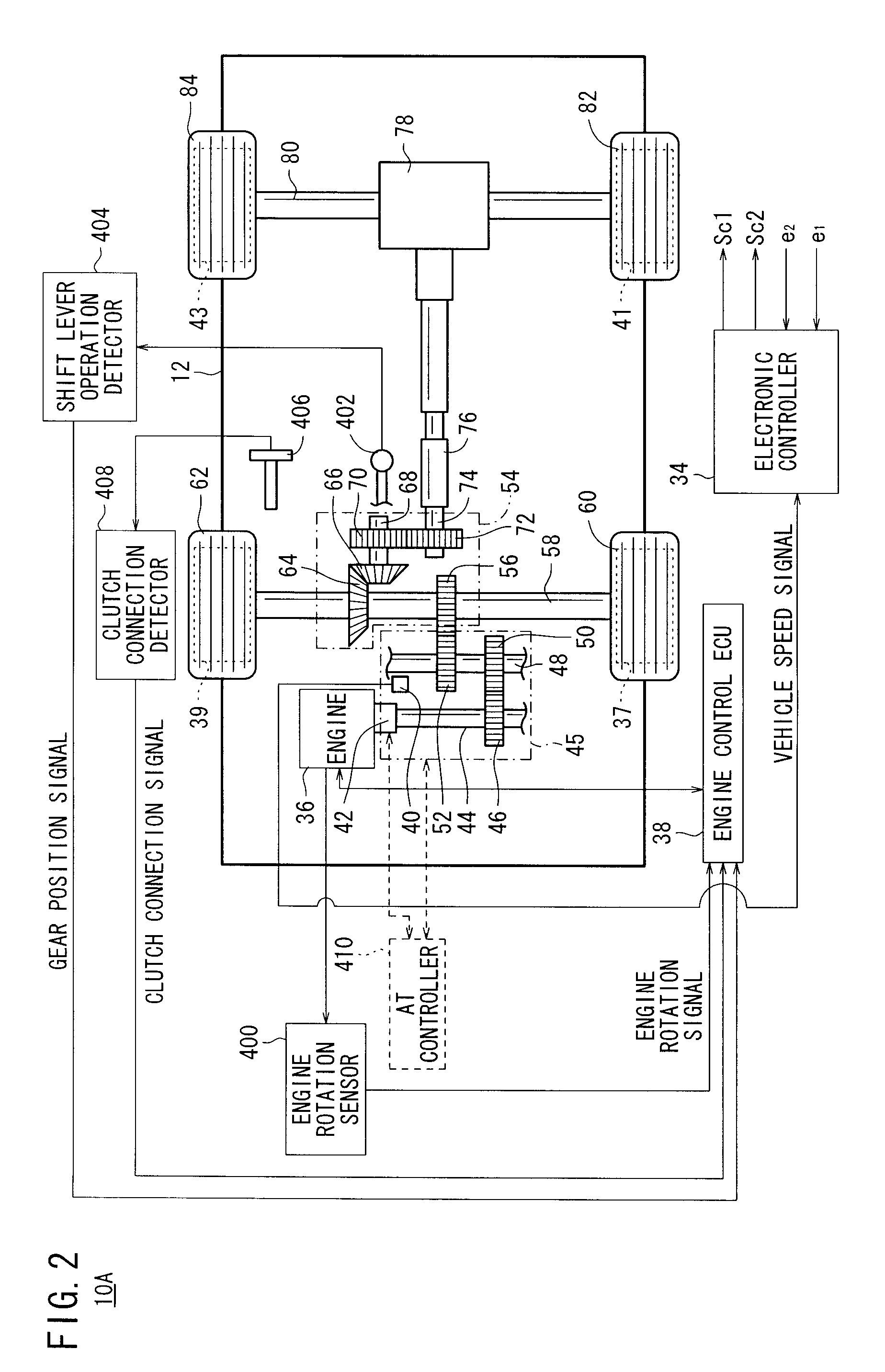
[0055]FIGS. 1 and 2 show in block form a vehicular active noise control system (hereinafter referred to as “system”) 10A according to the present invention, which is incorporated in a vehicle 12. In FIG. 2, the vehicle 12 is shown as a 4WD (AWD) vehicle.

[0056]The system 10A comprises a microphone 22 disposed on a roof lining of the vehicle 12 near the head rest 18 of a front seat 16 in a passenger compartment 14, or specifically near the position of an ear of a passenger, not shown, seated on the front seat 16, a microphone 28 disposed near the head rest 26 of a rear seat 24, a speaker 30 mounted on a door near the front seat 16, a speaker 32 disposed behind the rear seat 24, and an electronic controller 34.

[0057]The vehicle 12 has an engine 36 that is controlled by an engine control ECU 38. The engine control ECU 38 is supplied with an engine rotation signal from an engine rotation sensor (engine rotational speed detector) 400. The engine rotation signal is made up of engine rotati...

second embodiment

[0104]In FIGS. 7 and 8, if the vehicle 12 is an automatic transmission vehicle, then the AT controller 410 supplies the electronic controller 34 with the gear position signal and the clutch connection signal. However, it is assumed that the vehicle 12 is a manual transmission vehicle in the second embodiment and other subsequent embodiments.

[0105]When the switch controller 302 is supplied with the clutch connection signal from the engine control ECU 38, the switch controller 302 outputs a disconnection signal Ss indicating that the clutch 42 has disconnected the transmission 45 from the engine 36, to the control circuit 104 and the switch 300. When the disconnection signal Ss is not input to the switch 300, the switch 300 is turned on, supplying the engine rotation signal to the control circuit 104. When the disconnection signal Ss is input to the switch 300, the switch 300 is turned off, stopping supplying the engine rotation signal to the control circuit 104.

[0106]When the disconn...

third embodiment

[0114]A system 10C according to the present invention will be described below with reference to FIGS. 10 through 12.

[0115]In the system 10C, the electronic controller 34 is supplied with the vehicle speed signal from the vehicle speed sensor 40, and is also supplied with the engine rotation signal, the gear position signal, and the clutch connection signal from the engine control ECU 38. Based on the vehicle speed signal, the engine rotation signal, the gear position signal, and the clutch connection signal, the electronic controller 34 generates control signals Sc1, Sc2. The electronic controller 34 has a switch 300 and a switch controller 302. The switch 300 is a selector switch which supplies the engine rotation signal to the control circuit 104 when the disconnection signal Ss is not input to the switch 300, and supplies the vehicle speed signal to the control circuit 104 when the disconnection signal Ss is input to the switch 300.

[0116]When the disconnection signal Ss is not in...


PUM


Abstract

A frequency detecting circuit estimates the frequency fp of a propeller shaft based on the frequency fc of vehicle speed pulses, and calculates a control frequency fp′ which is a harmonic of the frequency fp. A basic signal generator generates a basic cosine wave signal xp1 and a basic sine wave signal xp2 of the control frequency fp′. Adaptive filters and an adder generate a control signal Scp for canceling a driveline noise produced in a passenger compartment by the propeller shaft. A speaker outputs a canceling sound based on the control signal Scp into the passenger compartment.

Description

BACKGROUND OF THE INVENTION[0001]1. Field of the Invention[0002]The present invention relates to an active noise control system for reducing an in-compartment noise caused by a vibratory noise generated by a vibratory noise source on a vehicle with a canceling sound that is in opposite phase with the in-compartment noise.[0003]2. Description of the Related Art[0004]Heretofore, there has been known the technology of an active noise control apparatus for reducing an in-compartment noise at the position of a microphone placed in the passenger compartment of a vehicle, by detecting the in-compartment noise with the microphone and outputting, from a speaker placed in the passenger compartment, a canceling sound that is in opposite phase with the in-compartment noise based on the in-compartment noise and an engine rotation signal which is correlated to the vibratory noise of an engine on the vehicle (see Japanese Laid-Open Patent Publication No. 2006-084532 and Japanese Patent No. 3843082...

Claims


Application Information

Patent Timeline
IPC IPC(8): G10K11/16
CPCG10K11/178G10K2210/1282G10K11/17823G10K11/17854G10K11/17857G10K11/17883
Inventor KOBAYASHI, YASUNORIINOUE, TOSHIOTAKAHASHI, AKIRASAKAMOTO, KOSUKE
Owner HONDA MOTOR CO LTD
Learn More