Al technical title is built by PatSnap Al team. It summarizes the technical point description of the patent document.
A technology of flanges and mounting holes, applied to parts of color TVs, parts of TV systems, TVs, etc.
Inactive Publication Date: 2007-04-18
THOMSON LICENSING SA
View PDF4 Cites 0 Cited by
Summary
Abstract
Description
Claims
Application Information
AI Technical Summary
This helps you quickly interpret patents by identifying the three key elements:
Problems solved by technology
Method used
Benefits of technology
Problems solved by technology
The viewing part has a luminous line screen on its inner surface
Method used
Image
Click on the blue label to locate the original text in one second.
Reading with bidirectional positioning of images and text.
Examples
Embodiment Construction
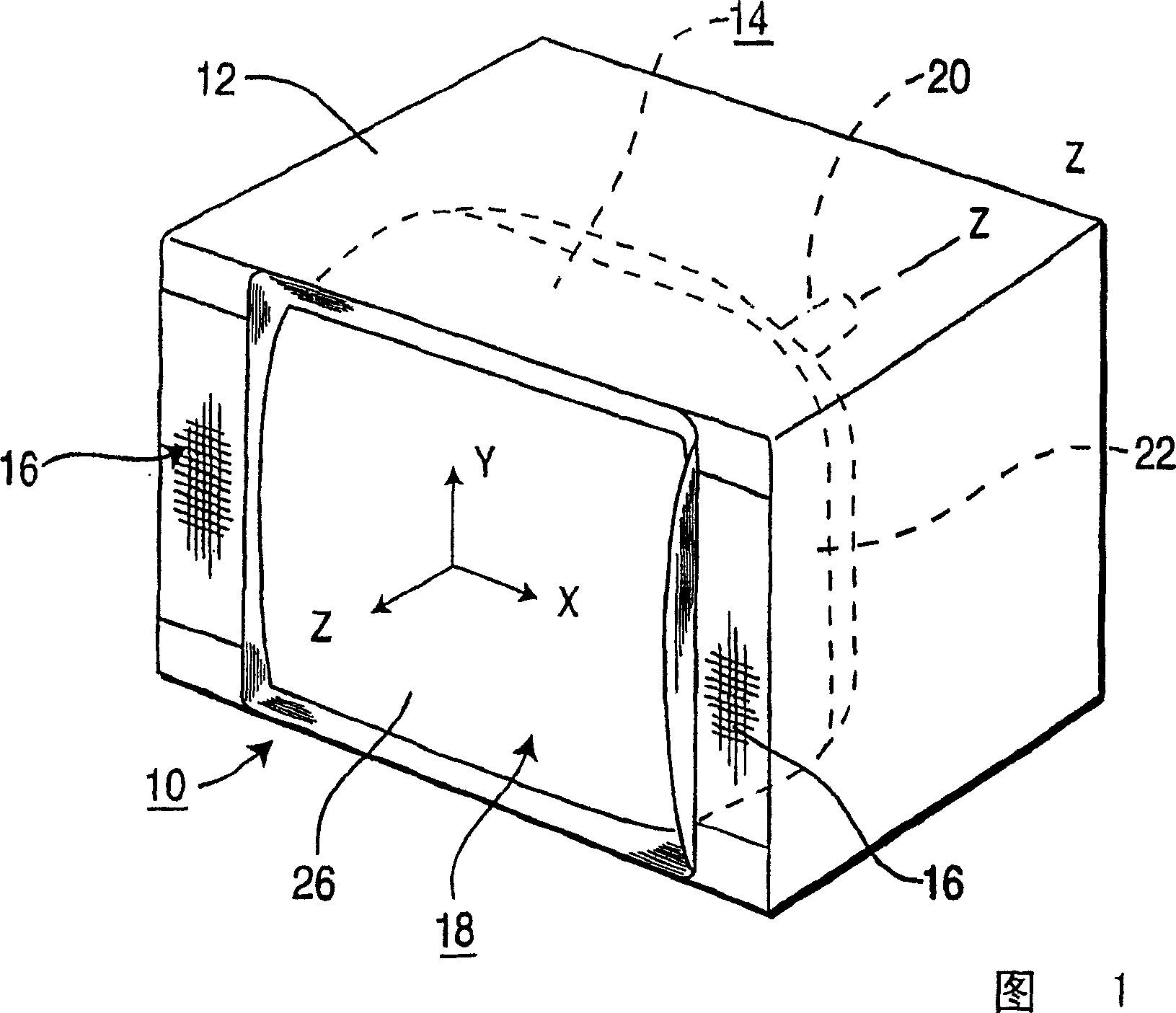
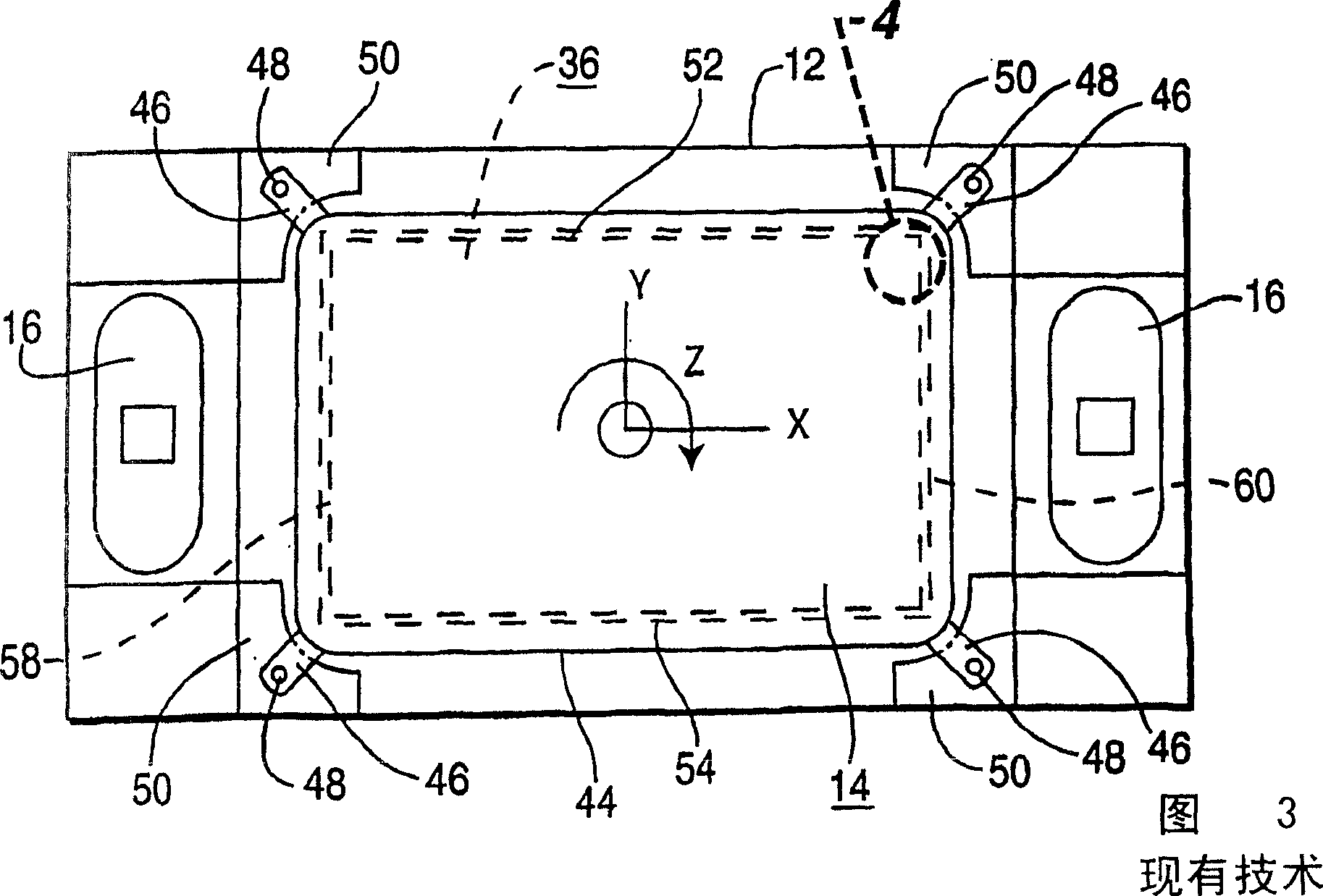
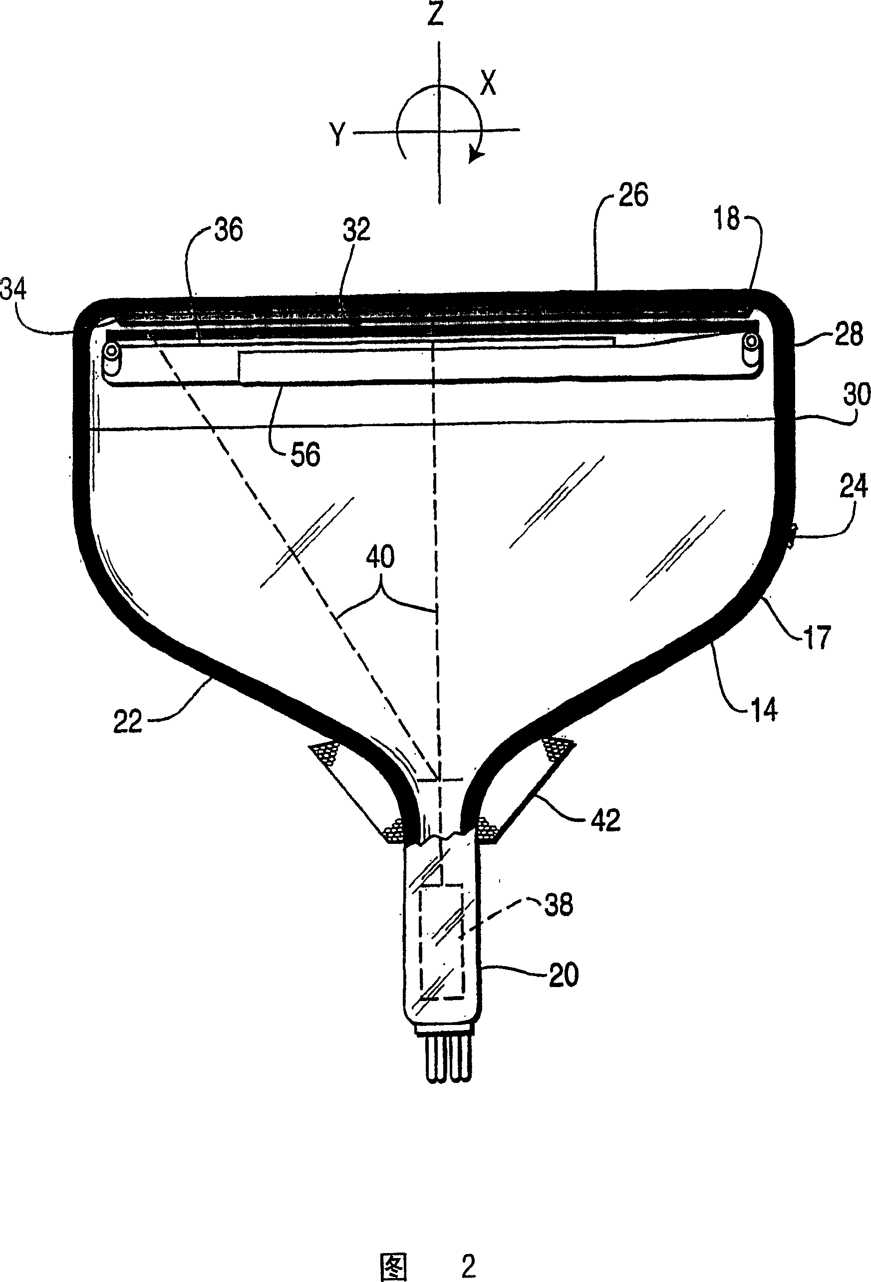
[0026] 1 shows a display device 10, such as a color television receiver, which includes a housing 12 within which a color CRT 14 and at least one audio speaker 16 are located. As shown in FIG. 2, a color CRT 14 includes an evacuated glass envelope 17 having a substantially rectangular face plate 18 and a tubular neck 20 connected by a rectangular funnel 22. As shown in FIG. Funnel 22 has an inner conductive coating (not shown) that contacts anode button 24 and extends therefrom to neck 20 and also toward face plate 18 . The panel 18 has a viewing portion 26 and a peripheral side wall 28 which is sealed to the funnel 22 with frit 30 . Viewing portion 26 of panel 18 includes a major axis X, which is parallel to the longer dimension of the viewing portion, and a minor axis Y, which is orthogonal to the major axis and parallel to the shorter dimension of the viewing portion of the panel. The CRT 14 additionally includes a central longitudinal axis Z which is orthogonal to the maj...
PUM
Abstract
A display apparatus 10 comprises at least one speaker 16 and a cathode-ray tube (CRT) 14 secured within an enclosure 12 to a plurality of mounting bosses 50. The cathode-ray tube 14 has an evacuated envelope 17 with a substantially rectangular-shaped faceplate panel 18 having four corners and a viewing portion 26 extending to a peripheral sidewall 28. The viewing portion 26 has a luminescent line screen 32 on the interior surface thereof The viewing portion 26 including two orthogonal axes, a major axis, X, parallel to a longer dimension of the viewing portion and a minor axis, Y, parallel to a smaller dimension of the viewing portion. The CRT 14 has therein an electron gun 38, capable of generating at least one electron beam, aligned along a central longitudinal axis, Z, of the CRT that is perpendicular to the major and minor axes. The CRT 14 also has a color selection electrode 36 in proximity to the interior surface of the viewing portion 26 of the faceplate panel 18. An implosion protection band 44 extends around the sidewall 28 of the faceplate panel 18. At least four mounting lugs 146, 246, 346, each having a base portion 148, 248, 348 and an attachment portion 150, 249-250, 350, with a mounting aperture 152, 251-252, 352, therethrough, cooperate with the implosion protection band 44 to facilitate securing the CRT 14 within the enclosure 12. The attachment portion 150, 249-250, 350, of each of the mounting lugs 146, 246, 346, is aligned along the central longitudinal axis, Z, of the CRT 14 and parallel to at least one of the two orthogonal axes, X, Y, to strengthen the attachment portion and reduce microphonics induced by the speaker 16.
Description
technical field [0001] The present invention relates generally to structures for supporting a display device, such as a color television picture tube, in an enclosure, such as a cabinet having at least one speaker, and more particularly, to providing greater support for a color television picture tube and reducing loudspeaker noise within the tube. Some component of the microphonic effect caused by the acoustic vibrations of the mounting lug. Background technique [0002] Cathode ray tubes (CRTs), such as color television picture tubes, are evacuated to very low pressures and are therefore susceptible to pressure implosion caused by atmospheric pressure acting on all surfaces of the tube. This problem has been addressed in the prior art by providing the CRT with an anti-implosion band which surrounds the face plate of the tube and applies a compressive force to it. The tube is supported within the enclosure using mounting lugs which are either integral with the implosion st...
Claims
Application Information
Patent Timeline
Application Date:The date an application was filed.
Publication Date:The date a patent or application was officially published.
First Publication Date:The earliest publication date of a patent with the same application number.
Issue Date:Publication date of the patent grant document.
PCT Entry Date:The Entry date of PCT National Phase.
Estimated Expiry Date:The statutory expiry date of a patent right according to the Patent Law, and it is the longest term of protection that the patent right can achieve without the termination of the patent right due to other reasons(Term extension factor has been taken into account ).
Invalid Date:Actual expiry date is based on effective date or publication date of legal transaction data of invalid patent.