
Method for inductive hardening of teeth of gearwheels

a gearwheel and inductive hardening technology, which is applied in the field of manufacturing a gearwheel, can solve the problems of time-saving manufacture of the gearwheel, and achieve the effect of efficient utilization of energy and simple implementation

Inactive Publication Date: 2015-10-13
SIEMENS AG
View PDF21 Cites 0 Cited by
  • Summary
  • Abstract
  • Description
  • Claims
  • Application Information

AI Technical Summary

Benefits of technology

This method streamlines the gearwheel manufacturing process, reducing inaccuracies and energy consumption by allowing continuous processing within a single clamping operation, enhancing precision and saving time while minimizing deformation.

Problems solved by technology

This procedure results in an especially time-saving manufacture of the gearwheel.

Method used


Image

  • Method for inductive hardening of teeth of gearwheels
  • Method for inductive hardening of teeth of gearwheels
  • Method for inductive hardening of teeth of gearwheels

Examples


Embodiment Construction

[0022]Throughout all the figures, same or corresponding elements may generally be indicated by same reference numerals. These depicted embodiments are to be understood as illustrative of the invention and not as limiting in any way. It should also be understood that the figures are not necessarily to scale and that the embodiments are sometimes illustrated by graphic symbols, phantom lines, diagrammatic representations and fragmentary views. In certain instances, details which are not necessary for an understanding of the present invention or which render other details difficult to perceive may have been omitted.

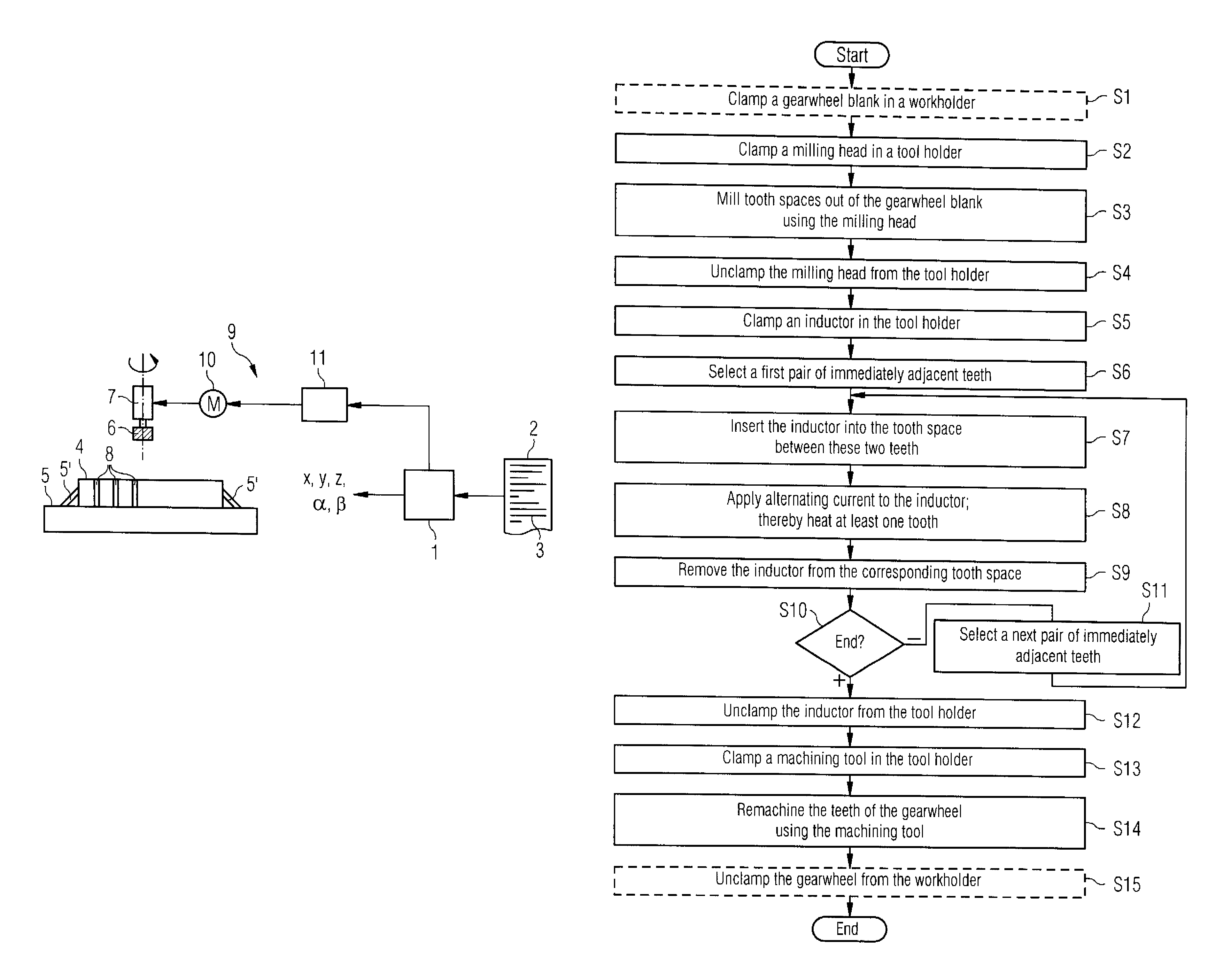
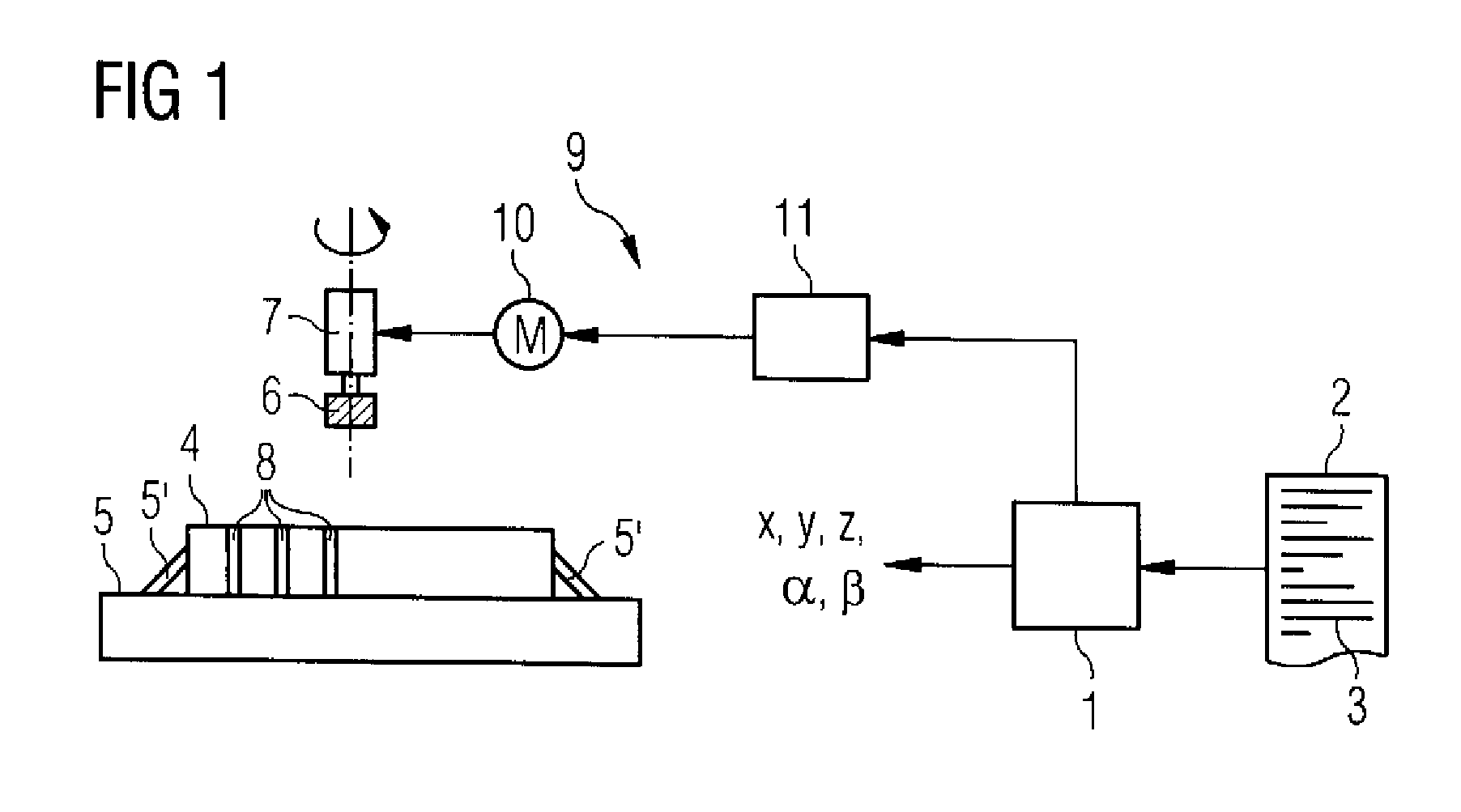
[0023]Turning now to the drawing, and in particular to FIG. 1, there is shown a schematic illustration of a multi-axis machine tool for executing a method according to the present invention. The multi-axis machine tool is controlled by a control device 1 and can be designed as required. In the non-limiting example of FIG. 1 the multi-axis machine tool 1 is designed as an at ...


PUM

PropertyMeasurementUnit
frequencyaaaaaaaaaa
frequencyaaaaaaaaaa
frequencyaaaaaaaaaa

Abstract

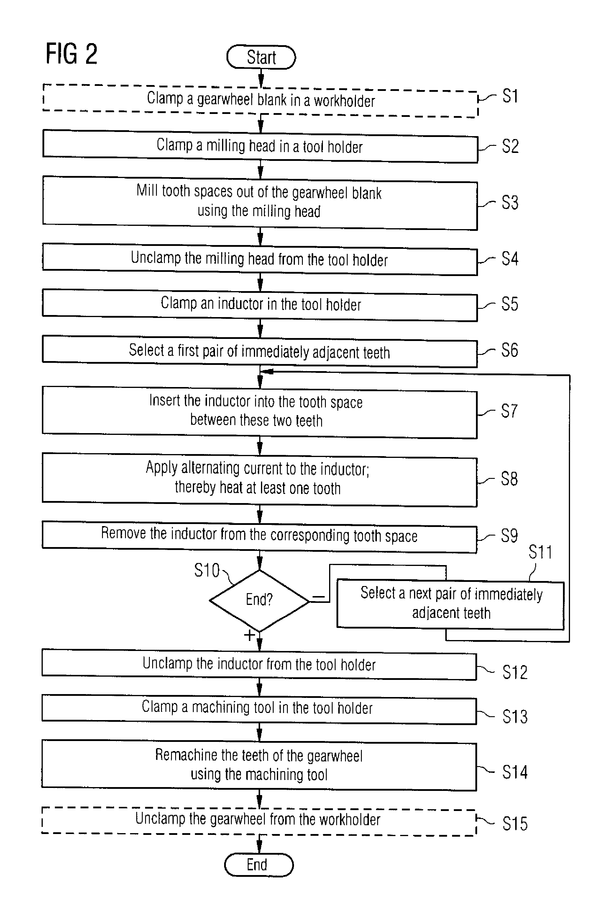
In a method for manufacturing a gearwheel, a gearwheel blank is clamped in a workholder of a multi-axis machine tool. A milling head is clamped in a tool holder which is rotated by a spindle drive to enable the milling head to mill out tooth spaces of the gearwheel blank to thereby create a gearwheel having teeth. After replacing the milling head in the tool holder with an inductor, the inductor is inserted successively between two adjacent teeth of the gearwheel and supplied with alternating current from a current supply device of the spindle drive to inductively heat at least one of the two adjacent teeth. The inductor in the tool holder is then replaced with a machining tool to remachine the teeth of the gearwheel.

Description

CROSS-REFERENCES TO RELATED APPLICATIONS[0001]This application claims the priority of European Patent Application, Serial No. EP 11193442, filed Dec. 14, 2011, pursuant to 35 U.S.C. 119(a)-(d), the content of which is incorporated herein by reference in its entirety as if fully set forth herein.BACKGROUND OF THE INVENTION[0002]The present invention relates to a process for manufacturing a gearwheel.[0003]The following discussion of related art is provided to assist the reader in understanding the advantages of the invention, and is not to be construed as an admission that this related art is prior art to this invention.[0004]Large gearwheels are generally manufactured as individual pieces or in small series. A gearwheel blank is hereby first clamped in a workholder of a special gear cutting machine. In this state tooth spaces are milled out of the gearwheel blank by a milling head, so that by milling out the tooth spaces from the gearwheel blank a gearwheel having teeth is produced....

Claims


Application Information

Patent Timeline
Patent Type & Authority Patents(United States)
IPC IPC(8): B23F17/00C21D1/42C21D9/32C21D1/10
CPCB23F17/006C21D1/10C21D1/42C21D9/32Y10T29/49476Y02P10/25
Inventor HAMANN, JENSKÖPKEN, HANS-GEORGROSENBAUM, BJÖRNULRICH, ANDREAS
Owner SIEMENS AG
Learn More