Mix door and vehicle air conditioner using the same

a technology for mixing doors and vehicles, which is applied in the direction of machine operation, wing accessories, light and heating apparatus, etc., can solve the problems of increasing flow resistance, wind noise, and increasing the risk of the evaporator being damaged by the mix door, so as to prevent the damage of the evaporator, the effect of increasing the flow resistance and preventing the noise caused by the gear portion

Active Publication Date: 2015-09-22
HIGHLY MARELLI JAPAN CORPORATION
View PDF13 Cites 0 Cited by
  • Summary
  • Abstract
  • Description
  • Claims
  • Application Information

AI Technical Summary

Benefits of technology

[0016]Moreover, the present invention provides a vehicle air conditioner configured such that an evaporator and a mix door are installed close to each other in this order from the upwind side inside a hollow air conditioner housing and that the evaporator is mounted into the air conditioner housing from an opening portion provided in a side surface of the air conditioner housing. In the vehicle air conditioner, a damage prevention guide portion is provided in a portion of the mix door closest to the evaporator, the damage prevention guide portion being capable of preventing damage on the evaporator by guiding the evaporator when the evaporator is inserted.
[0017]In the present invention, the following effects can be obtained from the configurations described above. Specifically, covering at least part of the gear portion provided in the gear mechanism portion with the gear cover can prevent the air for air conditioning from blowing directly on the gear portion. Accordingly, foreign objects such as debris and dust carried by the air for air conditioning can be prevented from being caught by the gear portion. Moreover, an increase in flow resistance and wind noise which are caused by the gear portion can be prevented.
[0018]Moreover, the evaporator can be guided by the damage prevention guide portion provided in the portion of the mix door closest to the evaporator, in such a way that the evaporator is not damaged when being inserted into the air conditioner housing.

Problems solved by technology

Therefore, there are risks that foreign objects such as debris and dust carried by the air for air conditioning are caught by the gear portion and that the gear portion located in the flow of the air for air conditioning causes wind noise and an increase in flow resistance.
Hence, when the evaporator is inserted into the air conditioner housing, there is a risk of the evaporator being damaged by the mix door.

Method used


Image

  • Mix door and vehicle air conditioner using the same
  • Mix door and vehicle air conditioner using the same
  • Mix door and vehicle air conditioner using the same

Examples


embodiment 1

[0032] A configuration is described below.

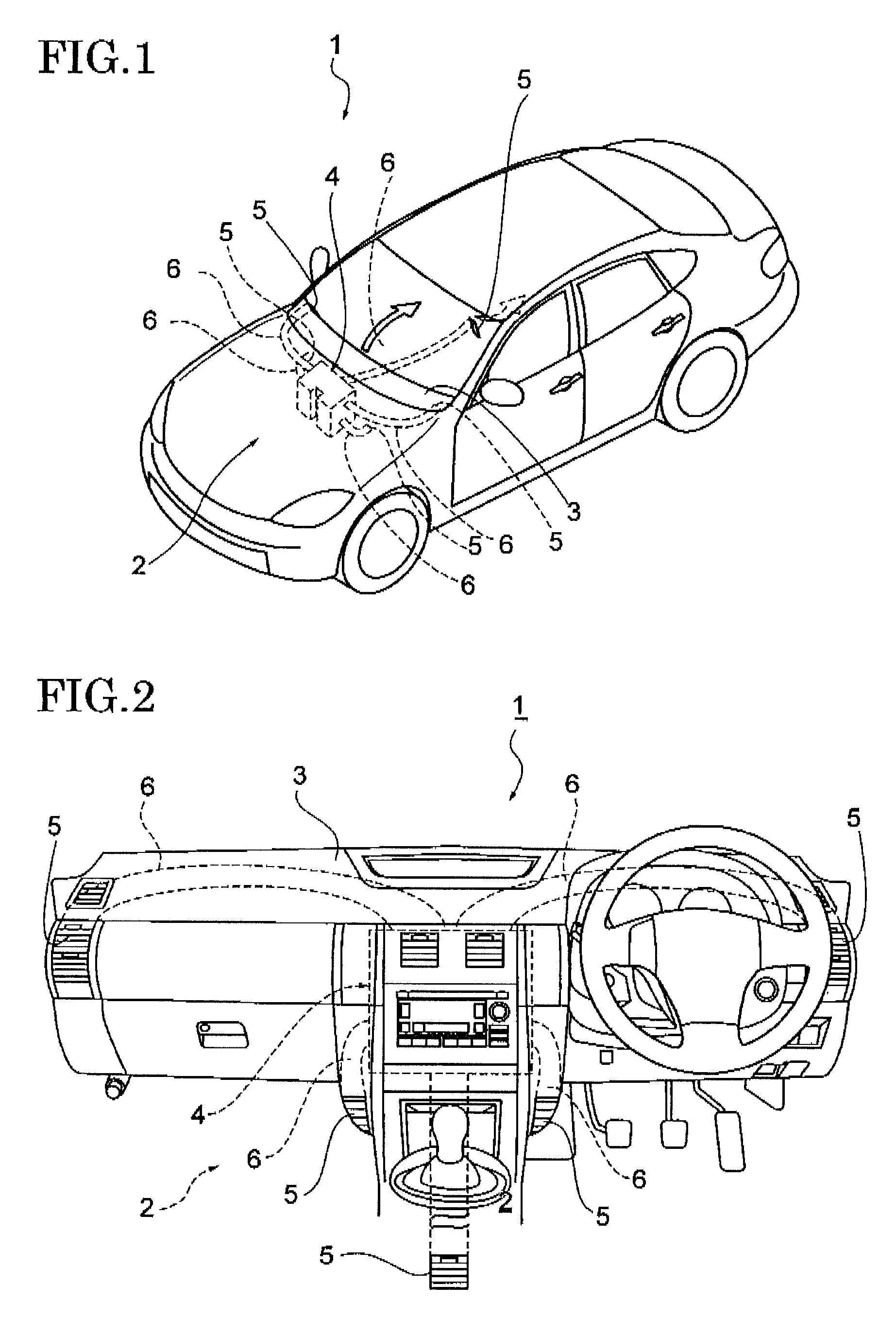
[0033]As shown in FIGS. 1 and 2, a vehicle 1 such as an automobile is provided with an air conditioning device (hereafter, referred to as air conditioner 2).

[0034]The air conditioner 2 includes an air conditioner main body 4 which is provided inside an instrument panel 3 installed in a front portion of a vehicle cabin and ducts 6 which send air for air conditioning from the air conditioner main body 4 to blow-out ports 5 provided in corresponding portions of the vehicle cabin.

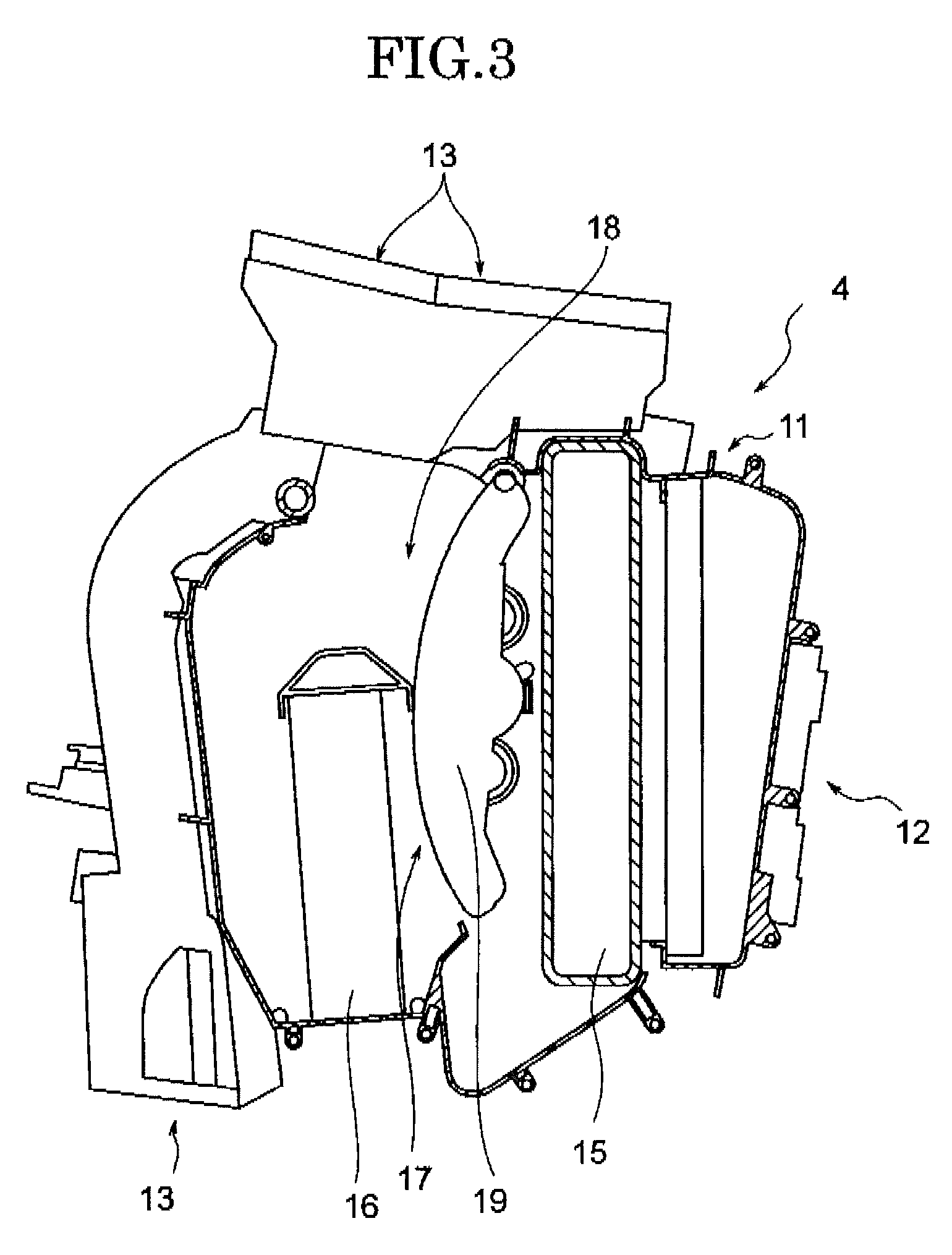
[0035]As shown in FIG. 3, the air conditioner main body 4 described above includes a hollow air conditioner housing 11 and an air intake port 12 and air discharge ports 13 provided in the air conditioner housing 11.

[0036]The hollow air conditioner housing 11 includes inside an evaporator 15 (heat exchanger for cooling) and a heater core 16 (heat exchanger for heating) in this order from the upwind side. A portion on the downwind side of the evaporator 15 is divided into...

embodiment 2

[0076] A configuration is described below.

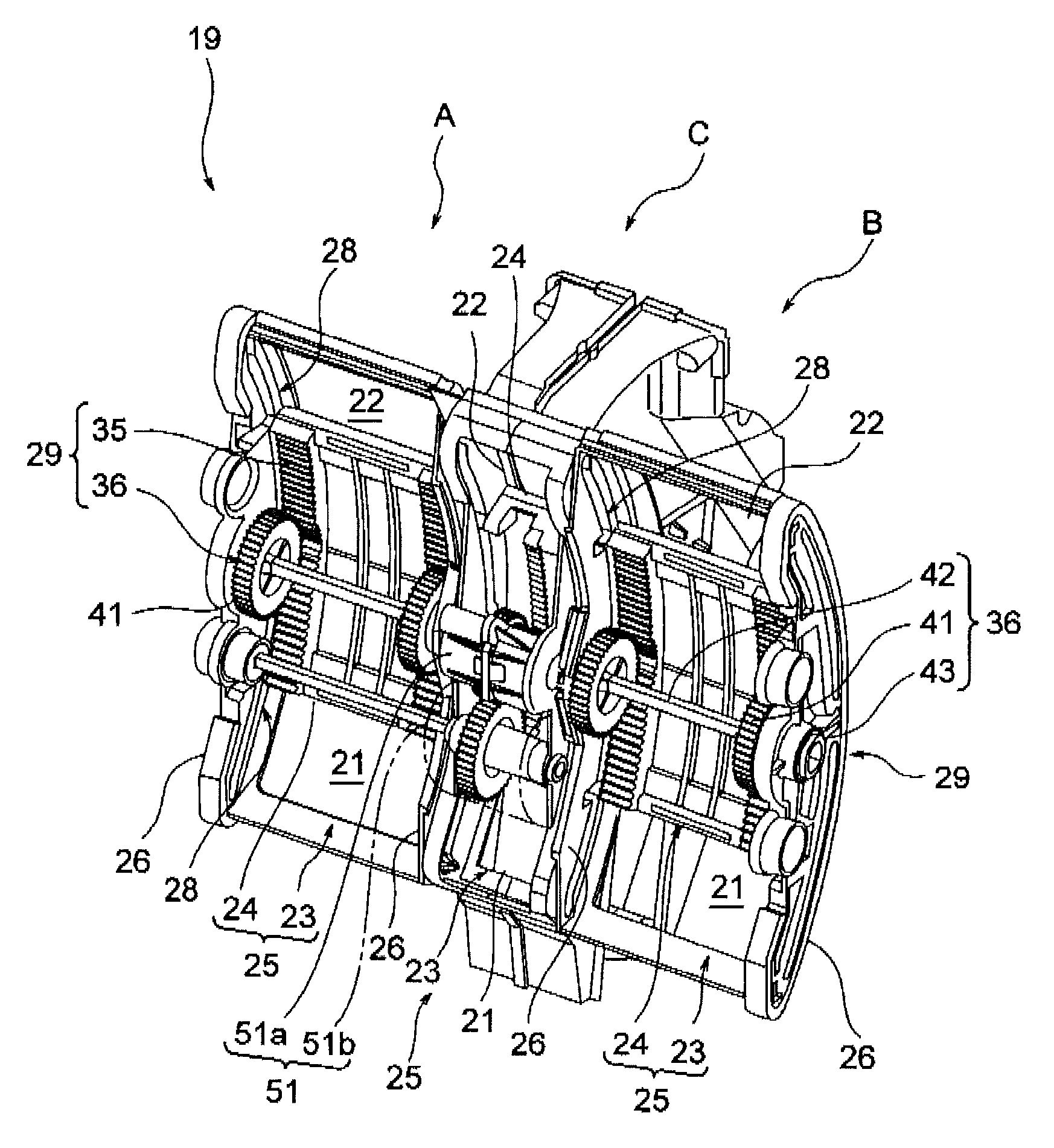
[0077]A hollow air conditioner housing 11 includes inside an evaporator 15 (heat exchanger for cooling) and a heater core 16 (heat exchanger for heating) in this order from the upwind side. A portion on the downwind side of the evaporator 15 is divided into a warm air passage 17 and a bypass passage 18 by a partition wall. The heater core 16 is provided inside the warm air passage 17. A mix door 19 is provided between the evaporator 15 and the heater core 16, the mix door 19 being capable of distributing an air for air conditioning having passed through the evaporator 15 to the warm air passage 17 and the bypass passage 18. The mix door 19 is installed at a position close to the evaporator 15.

[0078]The evaporator 15 is configured to cool the air for air conditioning by using evaporative latent heat of coolant used in an air conditioner 2. Moreover, the heater core 16 is configured to heat the air for air conditioning by using heat of cooling...


PUM


Abstract

A mix door includes a slide door unit, a slide driving part configured to drive the slide door unit, and a gear cover partially covering the slide driving part. The slide driving part includes a gear mechanism portion formed of a rack portion and a gear portion. The gear cover is provided to cover the gear portion.

Description

CROSS REFERENCE TO RELATED APPLICATIONS[0001]The present application is based on and claims priority from each of Japanese Patent Application Number 2011-151073, filed on Jul. 7, 2011, and Japanese Patent Application Number 2011-151075, filed on Jul. 7, 2011, the disclosure of which is hereby incorporated by reference herein in its entirety.BACKGROUND OF THE INVENTION[0002]1. Field of the Invention[0003]The present invention relates to a mix door and a vehicle air conditioner using the same.[0004]2. Description of the Related Art[0005]A vehicle such as an automobile is provided with an air conditioning device (hereafter, referred to as air conditioner) (for reference, see International Patent Application Publication No. WO20071061039 and Japanese Patent Application Publication No. 2001-270317).[0006]The air conditioner includes an air conditioner main body installed in a front portion of a vehicle cabin and ducts for sending air for air conditioning from the air conditioner main bod...

Claims


Application Information

Patent Timeline
Patent Type & Authority Patents(United States)
IPC IPC(8): F25B19/00B60H1/00
CPCB60H1/00692B60H1/00857
Inventor MAKITA, YUKIYANASHIMA, SHIZUKA
Owner HIGHLY MARELLI JAPAN CORPORATION
Why Eureka
Try Eureka