Spatial reconstruction of plenoptic images

a plenoptic imaging and image reconstruction technology, applied in the field can solve the problems of well-known, debilitating drawbacks of plenoptic imaging systems, and the lack of high-fidelity images of objects captured by plenoptic imaging systems, so as to improve the resolution estimate of objects, effectively inverting the pif operation, and enhance spatial resolution

Inactive Publication Date: 2015-09-15
RICOH KK
View PDF57 Cites 5 Cited by
  • Summary
  • Abstract
  • Description
  • Claims
  • Application Information

AI Technical Summary

Benefits of technology

[0009]Such linear inverse problems can be formulated and solved in various ways. For example, different distance measures may be used for the error calculation. Constraints on the object vector may be included as part of the minimization process. For example, if the object vector is composed of different components of the object (e.g., red, green and blue components of the object), the various components may have known relations to each other which could be enforced by using constraints in the minimization process. Different optimization techniques may be used to solve the minimization problem. Design choices of the matrix [PIFv] and selection of the optimization solving technique influence the quality of the estimated object vector [I*vo]. In one approach, the individual lenslets in the lenslet array in the plenoptic imaging system are non-centrosymmetric in order to improve the behavior of the inversion problem.
[0010]The PIF can be estimated or approximated using different approaches. A wave propagation approach is more accurate and includes diffraction effects. A geometrical optics approach is faster. The PIF may also be obtained by measurement of the optical response at the detector.

Problems solved by technology

However, a plenoptic imaging system is not designed to capture a high fidelity image of the object.
The loss of spatial resolution is a well-recognized and debilitating drawback of plenoptic imaging systems.

Method used


Image

  • Spatial reconstruction of plenoptic images
  • Spatial reconstruction of plenoptic images
  • Spatial reconstruction of plenoptic images

Examples


example pif

Based on Geometrical Optics

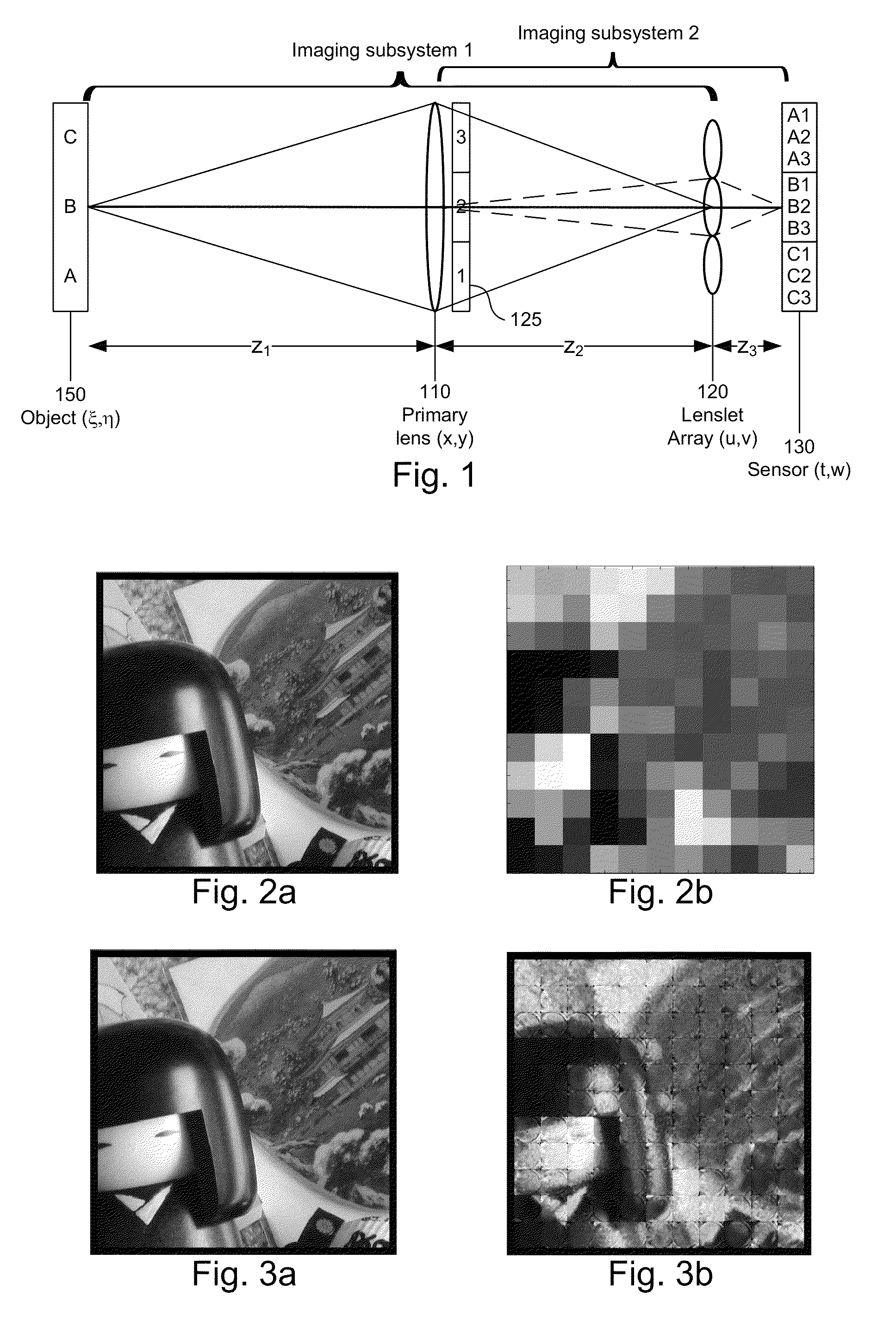
[0098]This derivation uses the nomenclature shown in FIG. 1 and the corresponding text. For convenience, the following derivation is one-dimensional. The extension to two dimensions is straightforward. The following definitions are also used:

[0099]λ Design wavelength

[0100]D Diameter of primary lens 110

[0101]F Focal length of primary lens 110

[0102]d Diameter of microlens 120

[0103]f Focal length of microlens 120

[0104]k Lenslet counter

[0105]R Radius of curvature of concave microlens surface

[0106]t Thickness of microlens

[0107]n Refractive index of microlens

[0108]W Sensor size

[0109]Δp Size of sensor pixel

[0110]δx Sampling interval in the object plane

[0111]2M Number of object samples

[0112]One geometrics optics approach is based on ray trace matrices. The basic ray trace matrix for the plenoptic imaging system of FIG. 1 is given by

[0113]S⁡[z3]⁢L⁡[-1f]⁢{tck}⁢S⁡[z2]⁢L⁡[-1F]⁢{tp*}⁢S⁡[z1](B⁢⁢1)

where S[ ] is the matrix for free space propagation and L[ ] is the matrix...


PUM


Abstract

The spatial resolution of captured plenoptic images is enhanced. In one aspect, the plenoptic imaging process is modeled by a pupil image function (PIF), and a PIF inversion process is applied to the captured plenoptic image to produce a better resolution estimate of the object.

Description

BACKGROUND OF THE INVENTION[0001]1. Field of the Invention[0002]This invention relates generally to plenoptic imaging systems, and more particularly to reconstruction of images and image components in plenoptic imaging systems.[0003]2. Description of the Related Art[0004]The plenoptic imaging system has recently received increased attention. It can be used to recalculate a different focus point or point of view of an object, based on digital processing of the captured plenoptic image. The plenoptic system also finds application in multi-modal imaging, using a multi-modal filter array in the plane of the pupil aperture. Each filter is imaged at the sensor, effectively producing a multiplexed image of the object for each imaging modality at the filter plane. Other applications for plenoptic imaging systems include varying depth of field imaging and high dynamic range imaging.[0005]However, a plenoptic imaging system is not designed to capture a high fidelity image of the object. Rathe...

Claims


Application Information

Patent Timeline
Patent Type & Authority Patents(United States)
IPC IPC(8): H04N5/225H04N5/232G06T5/00G02B7/34
CPCH04N5/23245H04N5/2254G02B7/34G06T5/003G06T2207/10052H04N23/60H04N23/667
Inventor SHROFF, SAPNA A.BERKNER, KATHRINMENG, LINGFEI
Owner RICOH KK
Why Eureka
Try Eureka